Table 5-1: cycle count register commands – PNI RM3000 Evaluation Board User Manual
Page 14
PNI Sensor Corporation
Doc #1015790 r03
RM3000 Evaluation Board User Manual
– June 2011
Page 14 of 19
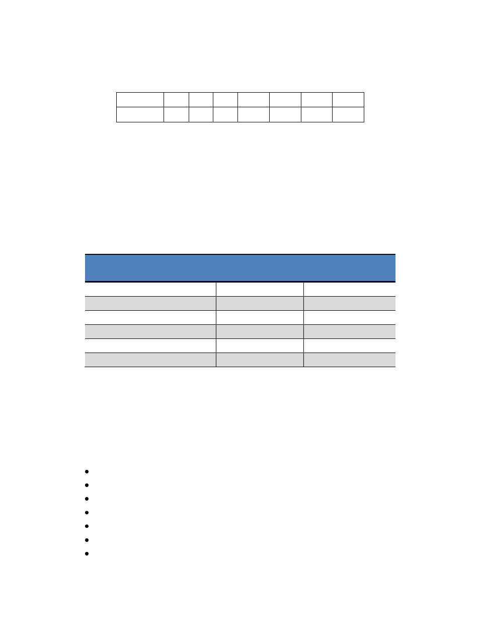
To initiate a read to or write from the Cycle Count Register, the command byte is defined as
follows:
7
6
5
4
3
2
1
0
RFLAG=1 R/W
0
0
ADR3 ADR2 ADR1 ADR0
R/W: Read/Write
HIGH signifies a Read operation from the addressed register. LOW signifies a Write
operation to the addressed register.
ADR0
– ADR3: Register Address Bits
Establishes which register will be written to or read from. Each sensor is represented
by two registers, with addresses defined as follows:
Table 5-1: Cycle Count Register Commands
Register Description
Read Command
Byte
Write Command
Byte
X Axis Cycle Count Value - MSB
C3H
83
H
X Axis Cycle Count Value - LSB
C4
H
84
H
Y Axis Cycle Count Value - MSB
C5
H
85
H
Y Axis Cycle Count Value - LSB
C6
H
86
H
Z Axis Cycle Count Value - MSB
C7
H
87
H
Z Axis Cycle Count Value - LSB
C8
H
88
H
Since the registers are adjacent, it is not necessary to send multiple Command Bytes, as the
RM3000 Evaluation Board automatically will read/write to the next adjacent register.
A sample command sequence is provided below which sets the cycle count value to 100
D
(64
H
) for all 3 axes. This is purely for illustrative purposes and the value could be different
and/or the number of axes to be addressed could be different.
Start with SSN set HIGH, then set SSN to LOW.
Send 83
H
(this is the Write Command Byte to address the MSB for the X axis)
Send 0 (value for the MSB for the X axis)
Send 64
H
(value for the LSB for the X axis - pointer automatically increments)
Send 0 (value for the MSB for the Y axis - pointer automatically increments)
Send 64
H
(value for the LSB for the Y axis - pointer automatically increments)
Send 0 (value for the MSB for the Z axis - pointer automatically increments)