Mam axes select byte, Making a multi-axis measurement, Table 5-3: mam axes select bits – PNI RM3000 Evaluation Board User Manual
Page 18: 3 mam axes select byte, 4 making a multi-axis measurement
PNI Sensor Corporation
Doc #1015790 r03
RM3000 Evaluation Board User Manual
– June 2011
Page 18 of 19
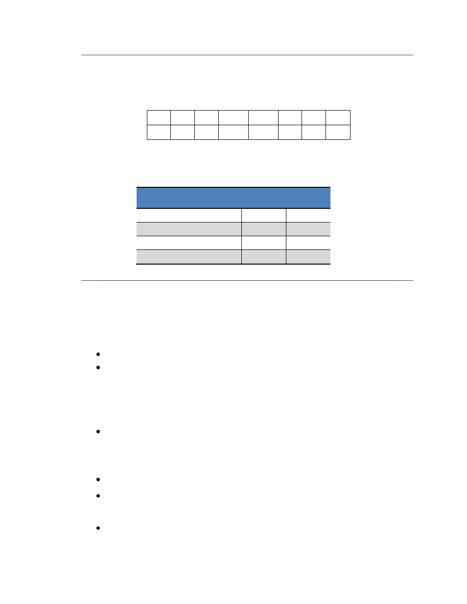
5.3.3 MAM Axes Select Byte
The MAM Axes Select Byte establishes which axes are to be measured and is defined as
follows:
Bit #
7
6
5
4
3
2
1
0
Value
0
0
0
AAX1 AAX0
0
0
1
Table 5-3: MAM Axes Select Bits
Axes to be Measured
AAX1
AAX0
X, Y, and Z
0
0
X and Y
0
1
X only
1
0
No axis measured
1
1
5.3.4 Making a Multi-Axis Measurement
The steps to make a multi-axis sensor measurement are given below. The RM3000
Evaluation Board will return the result of a complete forward- reverse measurement of
each sensor in a 24 bit 2’s complement format (range: -8388608 to 8388607).
Start with SSN set HIGH, then set SSN to LOW.
Initiate a sensor measurement by sending 82
H
(MAM Command Byte to write to
the Mode Register) followed by 01
H
(Mode Register Word to initiate
measurement) on the MOSI pin. The RM3000 Evaluation Board will now take
the prescribed measurements.
Return SSN to HIGH. This will not affect the measurement process, but will free
up the host to communicate with other devices and ensure the next Command
Byte sent to the module is interpreted properly.
A measurement is taken.
At the end of the measurement, the DRDY pin is set HIGH, indicating data is
ready, and the RM3000 Evaluation Board is placed in Idle Mode.
When the host is ready to read the measured values, set SSN to LOW. If SSN
already is LOW, then toggle SSN from LOW to HIGH to LOW.