5 vdc, Connections – PNI ASIC User Manual
Page 6
PNI ASIC
Theory of Operation
CONNECTIONS
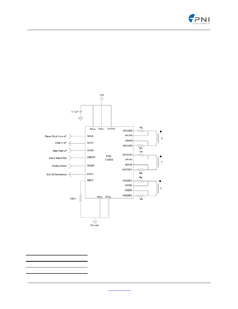
A typical connection configuration is shown in Figure 4 with the analog and digital sections of the PNI
ASIC tied together. This configuration is adequate for compassing applications. For higher performance
applications where less noise is desirable, separating the sections is recommended. The PNI ASIC can
control up to three sensors; if less are needed, the unneeded pins should be left to float.
The VSTBY pin must always be equal to or higher than any voltage present on any other ASIC pin.
VSTBY is connected to the cathode end of a diode in the array. The anode end of each diode in the array
is connected to each of the digital interface signal pins. Leaving VSTBY floating or connected to ground
when other pins are potentially active, as in multiplexed SPI networks, will cause excessive current drain.
Figure 4: Typical Connections
Table 7: Rb Value Sufficient for Evaluation
SEN-XY
5 VDC
75 Ohm
3 VDC
43 Ohm
PNI Corporation 133 Aviation Blvd., Suite 101, Santa Rosa, CA 95403‐1084 USA;, Fax: (707) 566‐2261
For the most current specifications, please visit our website at:
www.pnicorp.com
‐ 6 ‐