Spi port usage tips – PNI ASIC User Manual
Page 10
PNI ASIC
Host Processor Interface
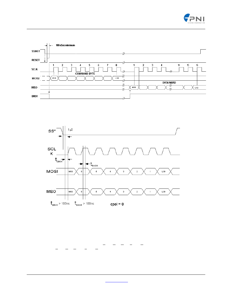
Figure 5: SPI Port Full Timing Sequence (cpol = 0 )
Figure 6: SPI Port Timing Parameters (cpol = 0)
SPI Port Usage Tips
A SPI port can be implemented using different clock polarity options. The clock polarity used with the PNI ASIC
must be normally low, (cpol = 0).
graphically shows the timing sequence (cpol = 0). Data is always
considered valid while the SCLK is high (t
DASH
= Time, Data After SCLK High). When SCLK is low, the data is in
transition (t
DBSH
= Time, Data Before SCLK High).
When implementing a SPI port, whether it is a dedicated hardware peripheral port, or a software implemented port
using general purpose I/O (also known as Bit-Banging) the timing parameters given in
must be met to
ensure reliable communications. The clock set-up and hold times, t
DBSH
and t
DASH
must be greater than 100 nS.
PNI Corporation 133 Aviation Blvd., Suite 101, Santa Rosa, CA 95403‐1084 USA;, Fax: (707) 566‐2261
For the most current specifications, please visit our website at:
www.pnicorp.com
‐ 10 ‐