NORD Drivesystems B4010 User Manual
Page 5
Замена шайб
Упругая
шайба
(507)
фиксирована
для
предотвращения осевого смещения. Снять винт с
цилиндрической головкой (519), нажимную шайбу
(518)
и стопорное кольцо (520). Вставить в
высверленное отверстие закрытую шайбу (I), что-
бы при отжимании не повредить центрирующую
резьбу на концевой цапфе вала. Надеть нажим-
ную шайбу (518), затем установить стопорное
кольцо (520). Нажимная шайба, стопорное кольцо
и винт с цилиндрической головкой для регулиро-
вочного шкива не входят в объем поставки.
В отверстии нажимной шайбы (518) имеется резь-
бовая нарезка, которая на один размер больше,
чем резьба винта с цилиндрической головкой (II).
Отжать упругую шайбу (507) или регулировочный
шкив (506). Очистить концевую цапфу вала, сма-
зать маслом или обработать дисульфидом
молибдена в аэрозольной упаковке. Насадить но-
вую упругую шайбу или регулировочный шкив,
вставить в шайбу стопорное кольцо (520), наса-
дить на вал новую упругую шайбу с нажимной
шайбой (519) и винтом с цилиндрической головкой
(519)
и зафиксировать. Избегать любых ударов.
Если при удалении регулировочного шкива или уп-
ругой
шайбы,
также
одновременно
прокручивается и нажимная шайба (518), зафик-
сировать нажимную шайбу расположенным в пазу
штифтом (III).
В конструкционном варианте модели с устройст-
вом для записи импульсов, датчик импульсов
служит к качестве стопора упругой шайбы в осе-
вом направлении.
Необходимо следить за тем, чтобы упругая шайба
и регулировочный шкив монтировались точно в
соответствии с чертежом, как показано выше, так
как перепутывание местами или слишком
сильное закручивание шайб может привести к по-
вреждению
отдельных
деталей.
Точное
местоположение
особенно
необходимо
соблюдать для конструкционного варианта
модели Z!
Необходимо, что движущиеся половинки шайб
должны всегда располагаться одна напротив дру-
гой.
Индикация частоты вращения
A.
Тип BLD
Вспомогательное напряжение: 230 В переменного
тока
±
10%, 50 / 60
Гц
Импульсный
вход:
устройство
располагает
обрабатывающим импульсы входом NPN-/PNP (U
L
≤
0,5 V ; U
H
≥
2,5 V;
макс. 24В) и NAMUR (R
EIN
=
1k).
Электроснабжение датчика:
на зажиме 4 9,1 оно составляет 15мА постоянного
тока.
B.
Тип BLA
Вспомогательное напряжение:
230
В / 110 В
±
10%
50 / 60
Гц
FGL 4 /. =
подключение для бесконтактного
измерения частоты вращения
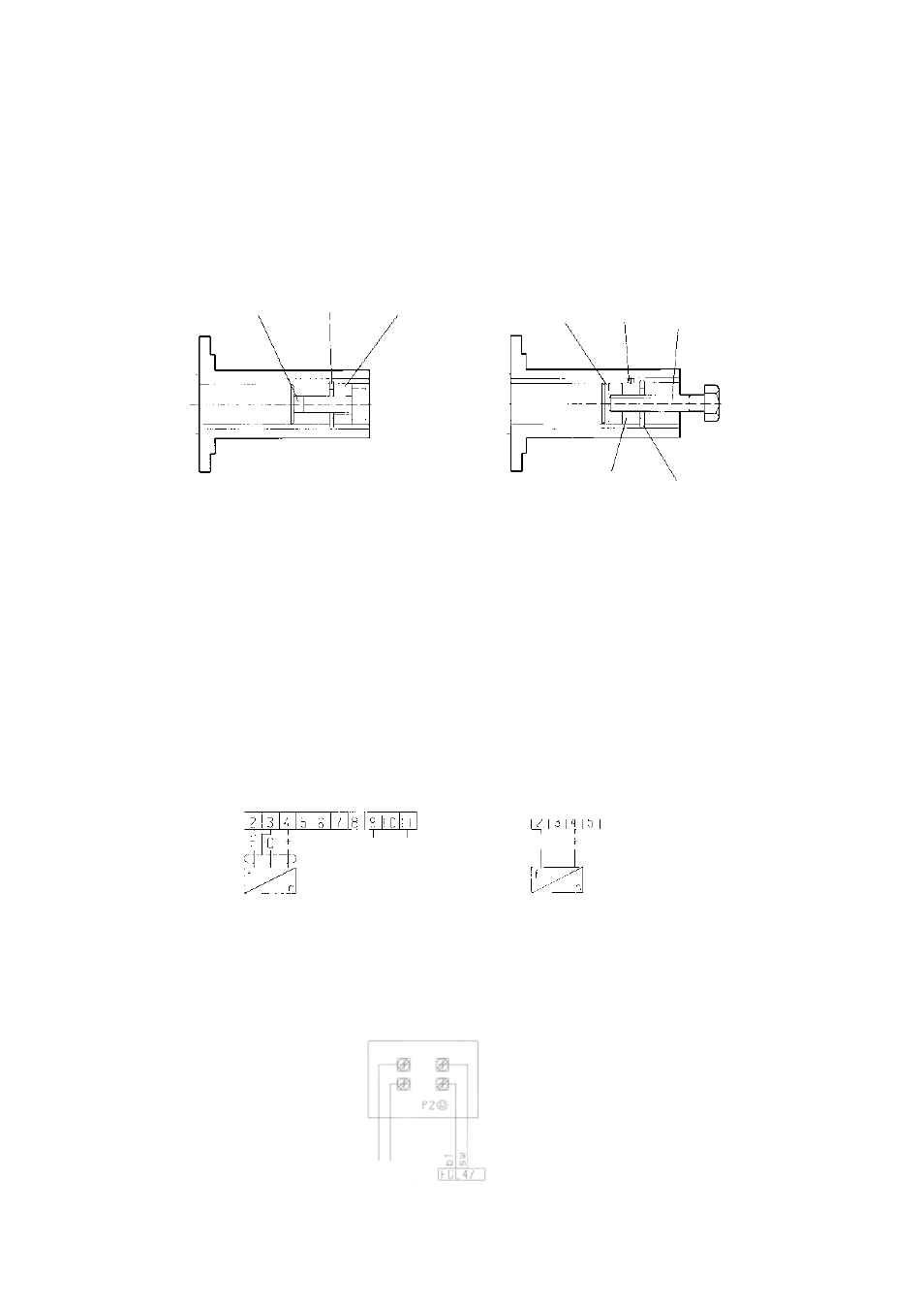
Replacement of Pulleys
The spring loaded pulley (507) is located securely on
the shaft by the screw (519), a thrust washer (518),
and a circlip (520). Remove the screw, washer and
circlip and place a steel disc (l) against the end of the
shaft to protect the tapped hole in the shaft.
Replace the thrust washer (518) and re-fit the circlip.
The thrust washer has an internal thread larger than
the screw (II) or spindle. Pull off spring loaded pulley
(507).
Before fitting the new pulley spray the shaft with a
Molykote compound. Assemble the thrust washer
(518) and circlip (520) into the pulley bore and pull
the pulley onto the shaft with the screw (519). Do not
drive the pulley on with force.
If the thrust washer (518) also rotates when
withdrawing the pulley, secure the thrust washer with
a pin (III) inserted in the keyway.
With units including NAMUR sensor, the pulse-
generator-disc secures the spring loaded pulley
axially on the shaft.
Please ensure the spring loaded and adjustable
pulleys are exactly mounted as described, otherwise
by assembling the wrong way round the pulleys can
be damaged. Special care has to be taken with Z-
design!
Please note that the moving parts of the pulleys must
be always situated on opposite (diagonal) sides.
Speed indicators
A. Type BLD
Auxiliary voltage:
230 V AC
±
10%
50 / 60 Hz
Impulse-Input:
The input of the BLD Indicator can process
NPN/PNP-Impulses (Impulse (U
L
≤
0,5 V ; U
H
≥
2,5 V;
max. 24V) and NAMUR (R
EIN
= 1k).
Supply to sensor:
At terminal 4 9,1 VDC/15mA.
B. Type BLA
Auxiliary voltage:
230 V / 110 V
±
10%
50 / 60 Hz
FGL 4/.=
connection for non-contacting
speed indicator
Scheibenwechsel
Die
Federscheibe
(507)
ist
gegen
axiale
Verschiebung gesichert. Zylinderschraube (519),
Druckscheibe (518) und Sicherungsring (520)
entfernen. In die Bohrung eine geschlossene Scheibe
(I)
einlegen,
um
beim
Abdrücken
das
Zentriergewinde
im
Wellenstumpf
nicht
zu
beschädigen.
Druckscheibe
(518)
einsetzen,
anschließend
Sicherungsring
(520)
montieren.
Druckscheibe, Sicherungsring und Zylinderschraube
für
die
Regelscheibe
gehören
nicht
zum
Lieferumfang.
Die Druckscheibe (518) hat in ihrer Bohrung ein
Gewinde, welches um eine Nummer größer ist als
das der Zylinderschraube (II). Feder-(507) oder
Verstellscheibe (506) abdrücken. Wellenstumpf
reinigen, einölen oder mit Molykotespray einsprühen.
Neue
Feder-
oder
Verstellscheibe
aufsetzen,
Sicherungsring (520) in die Scheibe setzen, die neue
Federscheibe
mit
Druckscheibe
(519)
und
Zylinderschraube (519) auf die Welle ziehen und
sichern. Jedes Schlagen ist zu vermeiden.
Falls sich die Druckscheibe (518) beim Abziehen der
Verstell/Federscheibe mitdreht, Druckscheibe durch
einen in der Nut liegenden Stift (III) sicern.
Bei Ausführung mit Impulsaufnehmer übernimmt der
Impulsgeber die axiale Sicherung der Federscheibe.
Es ist zu beachten, daß Feder- und Verstellscheibe
genau in der Anordnung wie oben bezeichnet
montiert werden, da Verwechseln oder Verdrehen
der Scheiben zur Zerstörung einzelner Teile führen
können.
Besonders bei Z-Ausführung genaue
Anordnung beachten!
Bitte
beachten,
daß
sich
die
beweglichen
Scheibenhälften immer diagonal gegenüberliegen
müssen.
Drehzahlanzeigen
A. Typ BLD
Hilfsspannung:
230 V AC
±
10%
50 / 60 Hz
Impuls-Eingang:
Das Gerät verfügt über einen Eingang, der NPN-
/PNP-Impulse (U
L
≤
0,5 V ; U
H
≥
2,5 V; max. 24V) und
NAMUR (R
EIN
= 1k) verarbeitet.
Sensorversorgung:
Sie beträgt bei Klemme 4 9,1 VDC/15mA.
B. Typ BLA
Hilfsspannung:
230 V / 110 V
±
10%
50 / 60 Hz
FGL 4 /. =
Anschluß für berührungslose
Drehzahlmessung
519
519
518
I
III
Подключение
Connection
Anschluß
Индикатор частоты вращения
Speed indicator
Drehzahlanzeiger
P2
Индикатор юстировки
P2 Adjustment-Indicator
P2 Justierungs-Anzeiger
Вход NPN / NPN-Input / NPN-Eingang
Вспомогательное напряжение
230
В переменного тока
Auxiliary voltage 230V AC
Hilfsspannung 230V AC
Вход NAMUR / NAMUR-Input / NAMUR-Eingang
230
В/V ~
II
518
520
520