Configuration, Led indicators – NORD Drivesystems TI 275281172 User Manual
Page 4
PROFINET IO Bus module – SK TU4-PNT-M12-C
4 / 8
TI 275281172 - 4913
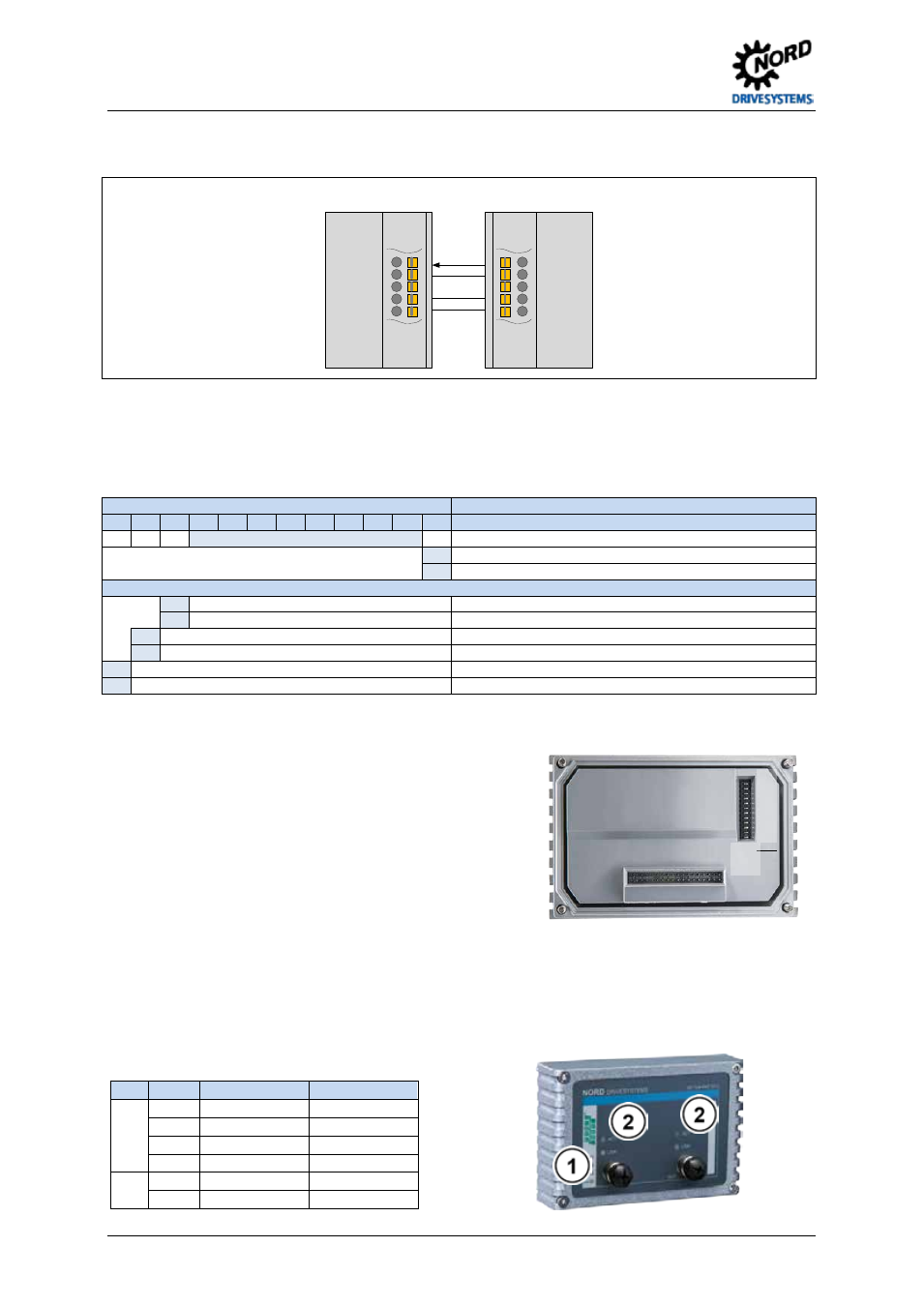
Schematic diagram - electrical connection
(Terminal designation on example of NORD frequency inverter SK 180E … SK 2xxE)
SK TI4-TU4 BUS
SK 180E … SK 2xxE
VI 24V
GND/0V
SYS +
SYS -
24V
GND/0V
SYS +
SYS -
Pos : 19 /T echnisc he I nf ormati onen/ SK xU x - Bus - Erweit erungen/ PROF INET IO /Konfiguration [ SK TU 4-PNT(-C(-M12))] @ 4\ mod_1385046026847_388. doc x @ 106049 @ 5 @ 1
Configuration
Configuration of the module for remote maintenance or for the system bus is carried out via the DIP
switches. The DIP - switch settings are read after a "Power On" of the module.
DIP switch
Meaning
12
11
10
9
8
7
6
5
4
3
2
1
X
X
X
No function
X
0
System bus terminating resistor not set
1
System bus terminating resistor set
Access rights for remote maintenance
0
Only read access to parameters possible.
1
Read and write access to parameters possible.
0
No control possible.
1
Control is possible.
0
TCP/IP open connection.
1
Secure TCP/IP connection.
1. System bus (DIP 1)
The system bus must be terminated at both physical
ends.
2. (DIP 2 - 9)
No function
3. Access rights for remote maintenance (DIP 10 – 12)
Via the Ethernet protocols TCP and UDP the module
and the connected frequency inverter can be
accessed using remote maintenance. The type of
access is determined via the DIP - switch with inputs
10 to 12.
Pos : 23 /T echnisc he I nf ormati onen/ SK xU x - Bus - Erweit erungen/ PROF INET IO /LED Anzeigen [SK TU 4-PNT-M 12(-C)] @ 4\ mod_1385377321045_388.doc x @ 106647 @ 5 @ 1
LED indicators
The operating statuses of the module are visualised using LED indicators.
No.
Name
Colour
Meaning
1
RUN
green
Ethernet State
BF
red
Ethernet Error
DS
green
Device status
DE
red
Device error
2
Link
green
Link
Act
yellow
Activity
1
…
12
ON
OF
F