Installation, Connections – NORD Drivesystems TI 275271019 User Manual
Page 3
EtherNet/IP Bus module – SK CU4-EIP
TI 275900150 - 4913
3
Pos : 8 /T ec hnis che Inf or mationen/ SK xU x - Bus - Er wei ter ung en/ Allgemein - Sys temübergreif end/M ont age [ SK CU 4-xxx] @ 3\ mod_1371811235059_388. doc x @ 79455 @ 5 @ 1
Installation
Installation location
Within the connection unit of a frequency inverter (SK 180E, SK 190E, 2xxE)
Mounting
with screw fastenings
Pos : 13 /T echnisc he I nf ormati onen/ SK xU x - Bus - Erweit erungen/ Allgemei n - Syst emübergreifend/ Ans chl üss e [ SK CU4 - .. .] @ 4\ mod_1378291237620_388. doc x @ 93067 @ 5 @ 1
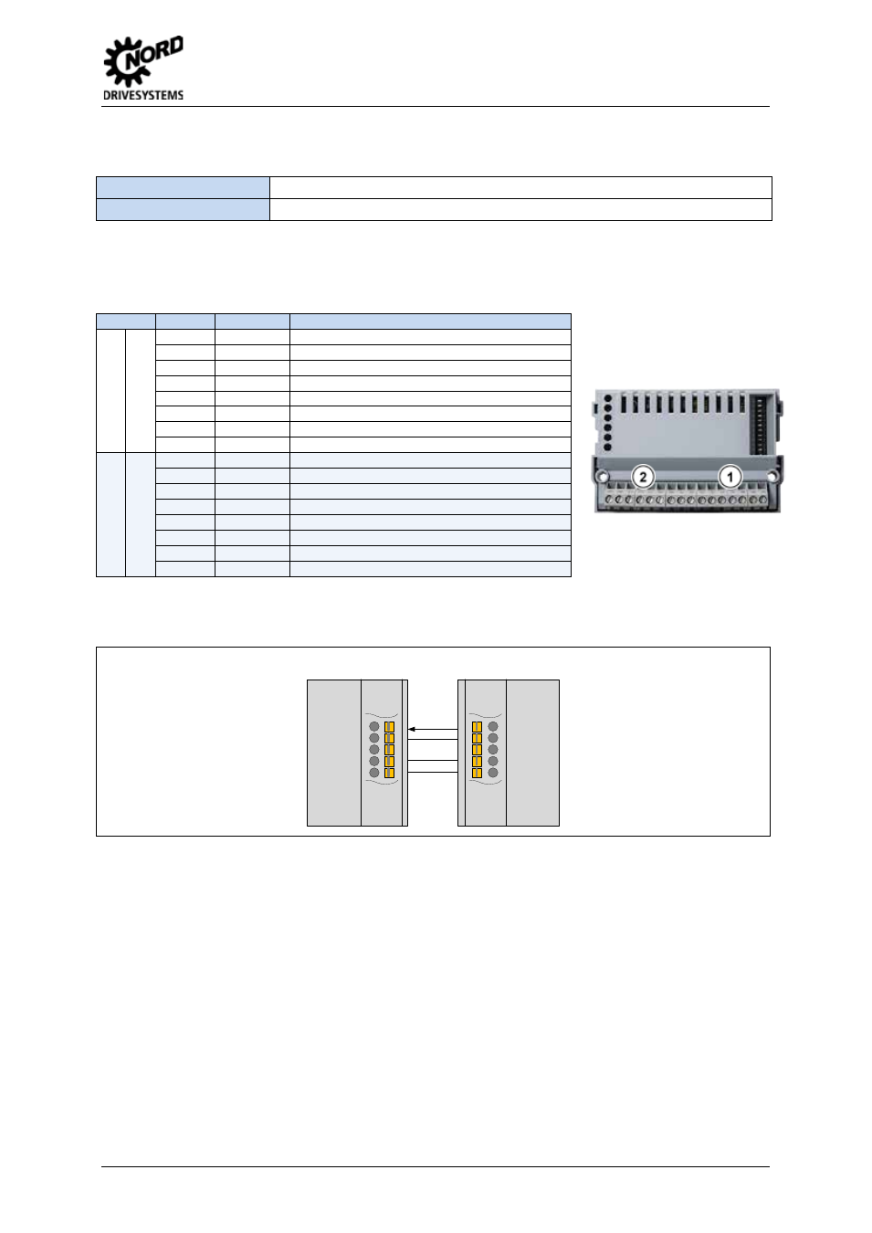
Connections
Connection is via the terminal bar of the module
Potential
Contact
Designation
Description
1
E
ther
ne
t
E8
PHY1 RX-
Ethernet connection 1 Receive Data -
E7
PHY1 RX+
Ethernet connection 1 Receive Data +
E6
PHY1 TX-
Ethernet connection 1 Transmission Data -
E5
PHY1 TX+
Ethernet connection 1 Transmission Data +
E4
PHY0 RX-
Ethernet connection 2 Receive Data -
E3
PHY0 RX+
Ethernet connection 2 Receive Data +
E2
PHY0 TX-
Ethernet connection 2 Transmission Data -
E1
PHY0 TX+
Ethernet connection 2 Transmission Data +
2
S
y
s
tem
b
us
l
e
v
el
and
di
gi
tal
i
np
ut
s
78
SYS -
System bus data line -
77
SYS +
System bus data line +
C1
DIN1
Digital input 1
C2
DIN2
Digital input 2
40
GND/0V
Reference potential (0 V / GND)
44
24V
Supply voltage (+24 V)
40
GND/0V
Reference potential (0 V / GND)
44
24V
Supply voltage (+24 V)
Schematic diagram - electrical connection
(Terminal designation on example of NORD frequency inverter SK 180E … SK 2xxE)
SK CU4-…
SK 180E … SK 2xxE
VI 24V
GND/0V
SYS +
SYS -
24V
GND/0V
SYS +
SYS -
Pos : 16 /T echnisc he I nf ormati onen/ SK xU x - Bus - Erweit erungen/ Et herN et/ IP/Konfigurati on [ SK CU4- EI P] @ 4\ mod_1384951929342_388. doc x @ 105681 @ 5 @ 1