The equipment, 20 kaman precision products – Kaman KDM-8200 User Manual
Page 20
20
Kaman Precision Products
The Equipment
Sensor
The table below lists the variable inductance sensors available for use with the
Specification KDM-8200 family and their standard performance specifications:
SENSOR
MODELS
MEASURING
RANGE
Inch (mm)
TYPICAL
OFFSET
Inch (mm)
ANALOG
VOLTAG
Vdc
DISPLACEMENT
SENSITIVITY
mV/mil (mV/mm)
FULL SCALE
MCD-8000
English (Metric)
.5U/.5U2
.020 (0.5)
.002 (.05)
2.00 (0.5)
100 (1000)
20.00 (_.500)
1U1/1U2
.040 (1.0)
.006 (.13)
.40 (1.0)
10 (1000)
_40.0 (1.000)
2S1
.080 (2.0)
.015 (.38)
.80 (2.0)
10 (1000)
_80.0 (2.000)
2UB1
.080 (2.0)
.015 (.38)
.80 (2.0)
10 (1000)
_80.0 (2.000)
2U2
.100 (2.5)
.025 (.63)
1.00 (2.5)
10 (1000)
100.0 (2.500)
3U1
.120 (3.0)
.020 (.51)
1.20 (3.0)
10 (1000)
120.0 (3.000)
4S1
.160 (4.0)
.020 (.51)
1.60 (4.0)
10 (1000)
160.0 (4.000)
6U1/6U2
.240 (6.0)
.035 (.89)
2.40 (0.6)
10 (1000)
240.0 (_6.00)
15U1/15U2
.600 (15)
.150 (3.81)
.60 (1.5)
1 (100)
_600. (15.00)
30U1/30U2
1.20 (30)
.300 (7.5)
1.20 (3.0)
1 (100)
1200. (30.00)
60U1
2.40 (60)
.600 (15)
2.40 (.60)
1 (100)
2400. (_60.0)
15N(diff)
±.009 (±.25)
.006 (.15)
±9.0 (±9.0)
1000 (36000)
±9.00 (.250)
20N(diff)
±.009 (±.25)
.006 (.15)
±9.0 (±9.0)
1000 (36000)
±9.00 (.250)
1925(HT)
.050 (1.27)
.005 (.127)
2.50 (2.5)
50 (2)
_50.0 (_1.27)
1925M(HT)
.040 (1.0)
.002 (.05)
2.00 (2.0)
50 (2)
_40.0 (_1.00)
1950 (HT)
.150 (3.81)
.010 (.254)
1.50 (1.50)
10 (400)
100.0 (_3.81)
1950M (HT)
.100 (2.54)
.005 (.127)
1.00 (1.00)
10 (400)
100.0 (_2.54)
1975 (HT)
.200 (5.00)
.010 (.254)
2.00 (2.00)
10 (400)
200.0 (_5.00)
1975M (HT)
.100 (2.54)
.005 (.127)
1.00 (1.00)
10 (400)
100.0 (_2.54)
Note: “_xx.x” indicates that the left-most display character (for higher resolution) is not available at the
scale factor selected due to limitations of the meter. The meter has a minimum input requirement of 200
microvolts per count.
•
The first digit in the sensor number indicates the specified linear measuring range in millimeters. (The
conversion factor from inches to millimeters is .03937.)
•
The letters “S” and “U” indicate whether the sensors are shielded or unshielded.
•
Other sensors, including differentially operating ones are available. If your application requires one of these
sensors, a special supplement to this manual will be made available.
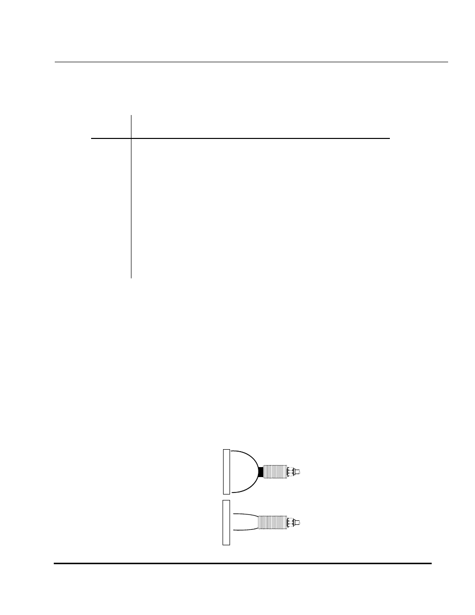
Measuring
The specified linear measuring range for an inductive system is directly proportional to
Range
the diameter of that sensor. Changes in oscillator frequency or power to the sensor normally have
no effect on measuring range. For any given sensor diameter, unshielded sensors have a greater
measuring range than shielded sensors. This is because the sensor’s field will “couple” with the
shield, in effect limiting the amount of field available for interacting with the target.
TARGET =
2.5 to 3X diameter of
an unshielded sensor
UNSHIELDED SENSOR
SHIELDED SENSOR
TARGET =
1.5 to 2X diameter of
an shielded sensor