Valve body assembly, Continued) – Dwyer 38R User Manual
Page 13
REPLACING Valve Body Assembly
1. Unless already completed, install two locknuts onto valve stem.
A) Thread locknuts loosely onto the valve stem.
B) Push or pull the valve stem as appropriate to fully CLOSE a two
way valve. For a three-way valve pull the stem full OUT.
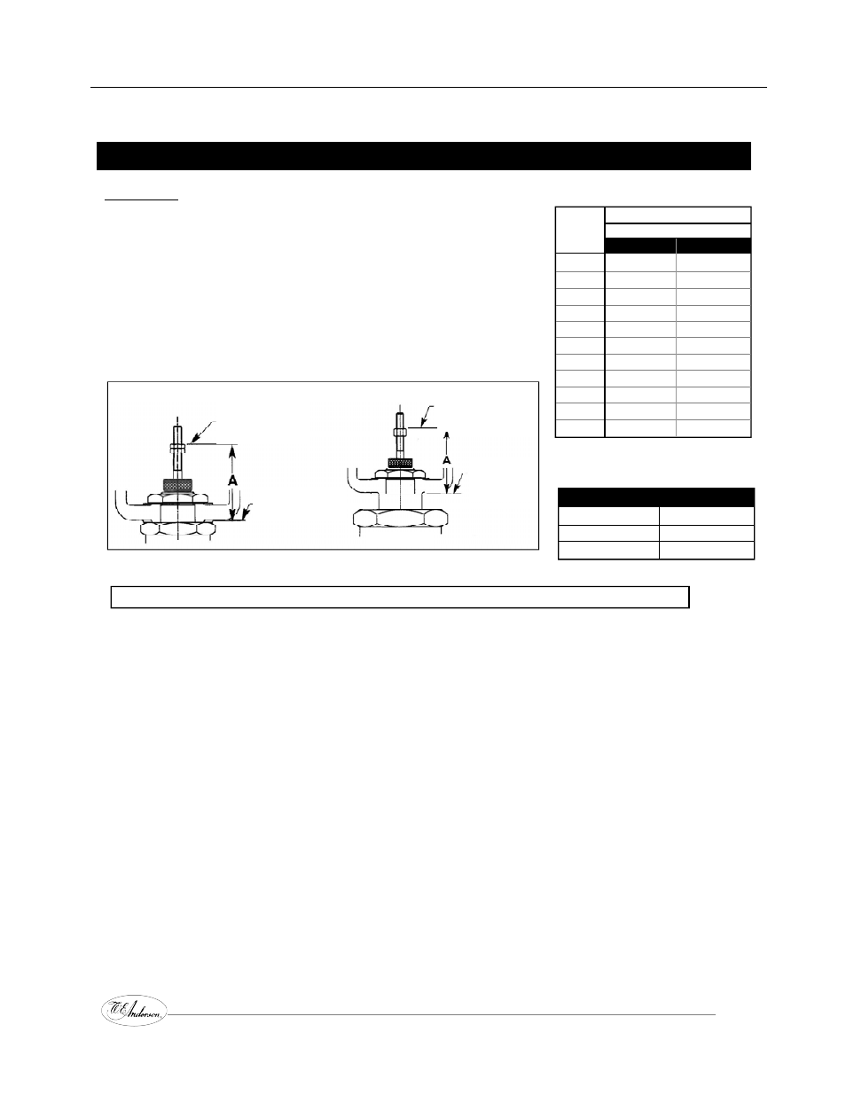
C) Set the topmost locknut to the dimension shown and tabulated
in Figure 6.
D) Tighten the lower locknut up against the upper locknut making
sure that the nuts are tight enough against each other to prevent
further turning about the valve stem.
Valve
Dim. A
Size
ACTION
NPT
IN to CLOSE
OUT to CLOSE
1
/
4
”-
1
/
2
”
2
1
/
4
”
2
3
/
8
”
3
/
4
”
2
3
/
16
”
2
3
/
8
”
1”
2
3
/
16
”
2
3
/
8
”
1
1
/
4
”
2
1
/
8
”
2
3
/
8
”
1
1
/
2
”
2
1
/
8
”
2
3
/
8
”
2”
2
1
/
8
”
2
3
/
8
”
2
1
/
2
”
2
1
/
8
”
2
3
/
8
”
3”
2
1
/
8
”
2
3
/
8
”
4”
2
1
/
8
”
2
3
/
8
”
5”
2
1
/
8
”
2
3
/
8
”
6”
2
1
/
8
”
2
3
/
8
”
* 2
1
/
2
” size valves and above
“A” Dimension is from top of spacer
to the top of Lock nuts.
3-Way Valves - Stem Out
Size - NPT
Dimension “A”
1
/
2
” thru 2”
2
3
/
8
”
2
1
/
2
” thru 6”
2
3
/
8
”
2.
Allow the sensing bulb on the actuator to cool to the bottom of the nominal range.
Artificially cool with ice if necessary.
3.
Record the current actuator adjusting screw setting relative to the reference scale.
4.
Turn the actuator adjusting screw in (up) to reference number 8.
5.
Place valve stem up through the Yoke and Bonnet Nut.
6.
Thread the valve stem into the actuator stem.
A. Use a 5/16” wrench to hold or turn the actuator stem.
B. Use a 3/8” wrench to hold the valve stem nuts to turn the valve stem.
DO NOT DIRECTLY GRIP THE ROUND POLISHED PORTION OF THE VALVE STEM.
If the valve plug can remain open relative to the valve seat, turn the valve stem into the actuator stem
until the locknuts are tight against the actuator stem.
If the valve plug is closed against the valve seat, then gently turn the actuator stem down onto the
valve stem until the actuator stem is tight against the locknuts.
IF FAIL-SAFE ACTUATOR MODEL SEE SPECIAL INSTRUCTIONS FOR ACTUATOR OPTION 3.
7.
Tighten the Bonnet Nut down onto the bonnet to hold the valve body assembly to the yoke.
Use a 1
1
/
2
” wrench.
8.
Return the actuator adjusting screw to the previously recorded reference setting.
VALVE BODY ASSEMBLY
(continued)
Series 38R ••• Self-Acting Temperature Control Valves
Operation, Installation & Maintenance Manual
Page 13
IF FAIL-SAFE ACTUATOR MODEL SEE SPECIAL INSTRUCTIONS FOR ACTUATOR OPTION 3.
1/2” - 2”
Lock Locknuts together
securely as tabulated
with valve fully closed.
Valves 2” and smaller
top of Bonnet Hex
2
1
/
2
” - 2”
Lock Locknuts together
securely as tabulated
with valve fully closed.
Valves 2
1
/
2
”
and larger
top of Spacer
Figure 6