Operation – Dwyer LIN-E-AIRE® User Manual
Page 6
6
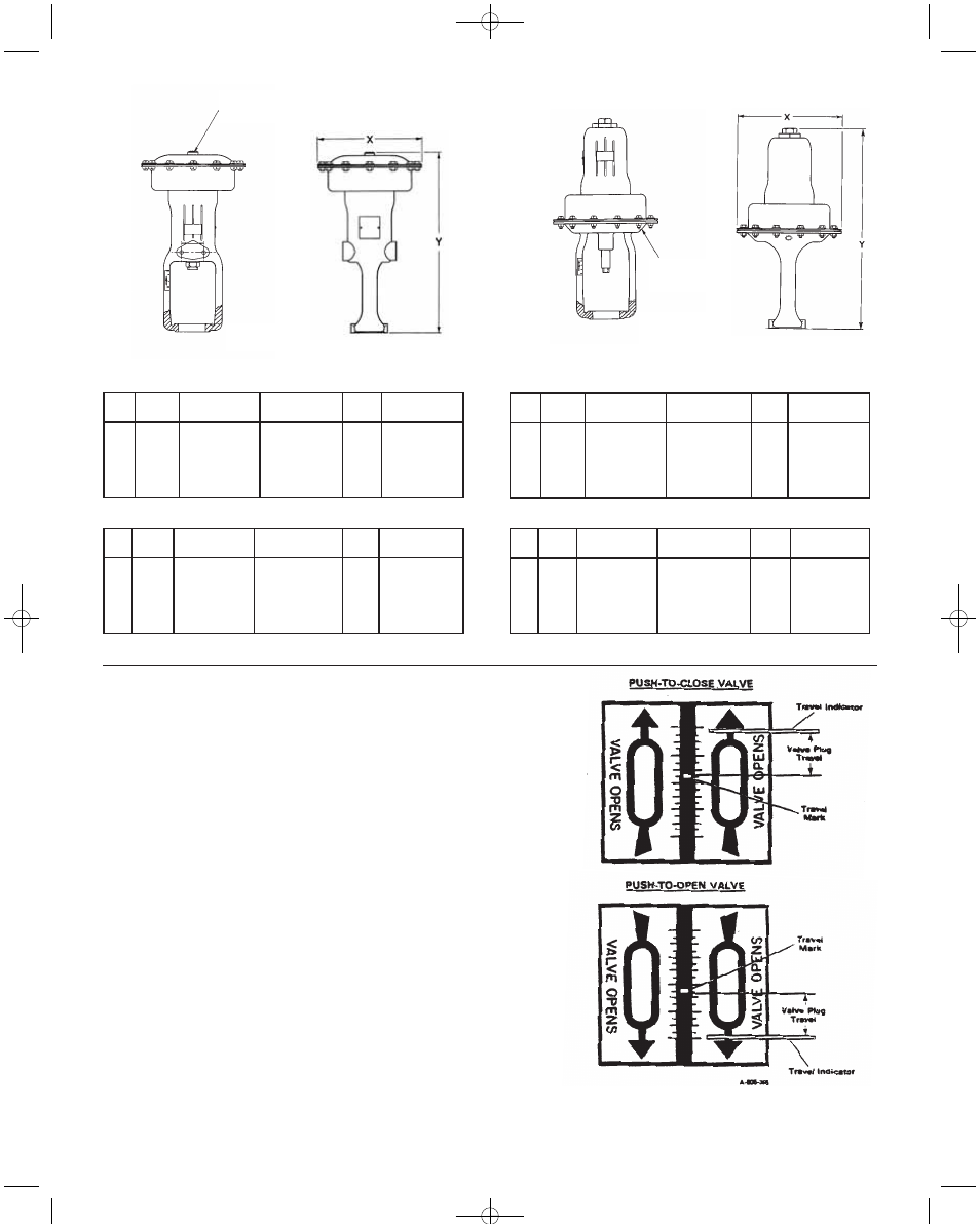
Figure 5. Travel Indicator Plate Showing Valve Plug Travel
3. OPERATION
3.1 Check Valve Travel - The actuator spring has been select-
ed to meet the requirements of the application and has been
adjusted at the factory to the pressure range stamped on the
data plate. The spring has a constant rate of compression, and
adjustments shift the pressure span up or down to make stem
travel coincide with this pressure range. When in service, the
actuator should yield the required travel when pressure range
stamped on data plate is applied. This diaphragm pressure range
is generally 3 to 15 psi (20 to 100 kPa), but other ranges may be
used.
When the actuator is completely installed and connected to the
control device, it should be checked with normal working line
pressure conditions for correct travel. Apply the pressure range
listed on the data plate to the actuator. Note that travel indicator
should have moved the distance marked on indicator plate,
Figure 5.
The pressure drop across the valve body ports has a direct effect
on the actual operating pressure range. In some instances, the
valve operating range may be different from the indicated range.
This is because the pressure conditions in the valve body are dif-
ferent from those originally specified and for which the control
valve has been set at the factory. If this difference is small, a
spring adjustment is all that is required to obtain correct operat-
ing range, refer to Adjusting Actuator Range.
Term
No.
220
222
240
242
244
Part
No.
15S620
15S622
15S640
15S642
15S644
X
7-3/4 (196.85)
10-5/8 (269.86)
7-3/4 (196.85)
10-5/8 (269.86)
13-3/8 (339.73)
Y
15-7/8 (403.23)
18-5/8 (473.08)
15-7/8 (403.23)
18-5/8 (473.08)
22-5/8 (574.68)
No. of
Bolts
10
12
10
12
18
Yoke Boss
Hole Diam.
1-1/2 (38.10)
1-15/16 (49.21)
2-1/8 (53.98)
2-13/16 (71.44)
2-13/16 (71.44)
Standard Actuator in. (mm)
Term
No.
221
223
241
243
Part
No.
15S621
15S623
15S641
15S643
X
10-5/8 (269.86)
13-3/8 (339.73)
10-5/8 (269.86)
13-3/8 (339.73)
Y
16-9/16 (420.69)
20 (508.00)
16-9/16 (420.69)
20 (508.00)
No. of
Bolts
12
18
12
18
Yoke Boss
Hole Diam.
1-1/2 (38.10)
1-15/16 (49.21)
2-1/8 (53.98)
2-13/16 (71.44)
Senior Actuator in. (mm)
For reference only; not for construction.
Term
No.
230
250
252
254
Part
No.
15S630
15S650
15S652
15S654
X
7-3/4 (196.85)
7-3/4 (196.85)
10-5/8 (269.86)
13-3/8 (339.73)
Y
17-3/16 (436.56)
17-3/16 (436.56)
20-3/4 (527.05)
32-7/32 (818.36)
No. of
Bolts
10
12
12
18
Yoke Boss
Hole Diam.
1-1/2 (38.10)
2-1/8 (53.98)
2-13/16 (71.44)
3-9/16 (90.49)
Standard Actuator in. (mm)
Term
No.
231
233
251
253
Part
No.
15S631
15S633
15S651
15S653
X
10-5/8 (269.86)
13-3/8 (339.73)
10-5/8 (269.86)
13-3/8 (339.73)
Y
17-13/16 (452.44)
22-9/32 (565.94)
17-13/16 (452.44)
22-9/32 (565.94)
No. of
Bolts
12
18
12
18
Yoke Boss
Hole Diam.
1-1/2 (38.10)
1-1/2 (38.10)
2-1/8 (53.98)
2-13/16 (71.44)
Senior Actuator in. (mm)
For reference only; not for construction.
Figure 3. Mounting Dimension for Air-to-Lower Actuator
Figure 4. Mounting Dimension for Air-to-Raise Actuator
Input Conn.
1/4˝ female NPT
Valve Body
Dimension
Input Conn.
1/4˝ female NPT
Valve Body
Dimension
IB-5A103:IB-5A103 1/29/10 11:37 AM Page 6