Installation – Dwyer LIN-E-AIRE® User Manual
Page 5
5
ACTUATOR MATERIALS
Frame: Cast Iron, Baked Enamel Finish.
Diaphragm Case: Steel, Baked Enamel Finish.
Diaphragm: Buna-N-rubber, Nylon reinforced.
Range Spring: Plated spring steel.
Range Spring Seat: Plated steel.
Adjusting Screw: Plated cold rolled steel.
Push Rod: Plated steel.
AMBIENT TEMPERATURE LIMITS
-32 to 150°F (-36 to 66°C).
MAXIMUM ACTUATOR AIR PRESSURE
Refer to Table 3.
AIR CONNECTION: 1/4˝ female NPT.
MAXIMUM STROKE
Refer to Table 3.
2. INSTALLATION
2.1 Mounting - The Lin-E-Aire
®
Valve Actuator is normally fur-
nished mounted on a valve body. Follow the valve body instruc-
tions when installing the control valve in the pipeline.
Clearance should be left above and below the control valve to
permit removal of actuator and valve plug. Removal clearance
dimensions are specified in the control valve instructions, as well
as installation instructions. The actuator will sometimes be
shipped alone for field mounting on a valve body. Mount actuator
as outlined in the control valve instructions.
2.2 Pneumatic Connections - Connect the input pressure to
the 1/4˝ female NPT port on the top of an air-to-lower actuator or
under the diaphragm casing on an air-to-raise actuator, Figure 3
or 4. Either pipe or tubing may be used for the air line. The input
pressure must not exceed the limits listed under the specifica-
tions.
When there is a long distance between the actuator and the con-
trol device which produces the input pressure, or when a large
actuator size is required, there may be excessive transmission lag
in the control signal. A W.E. Anderson Valve Positioner, Catalog
Number 100N or 165, can be used to reduce the lag. If a valve
positioner is included with the actuator, connections between the
positioner and actuator are made at the factory. Refer to the valve
positioner instructions for additional connection information.
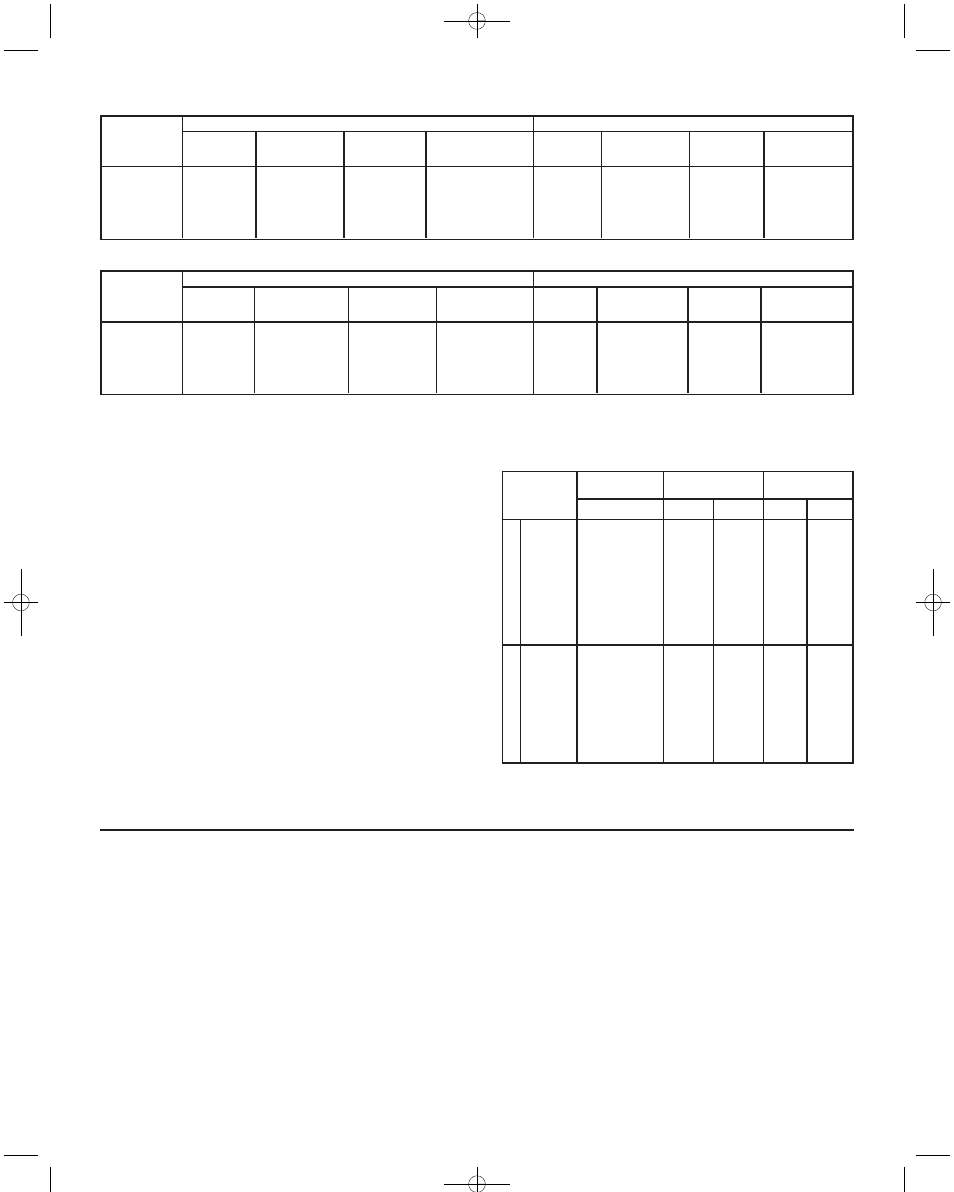
Boss
Dia.
1-1/2˝
1-15/16˝
2-1/8˝
2-13/16˝
2-13/16˝
Term.
No.
220
222
240
242
244
Part
No.
15S620
15S622
15S640
15S642
15S644
No. of
Bolts
10
12
12
12
18
Effective
Area
20 sq. in.
45 sq. in.
20 sq. in.
45 sq. in.
80 sq. in.
Term
No.
221
223
241
243
-
Part
No.
15S621
15S623
15S641
15S643
-
No. of
Bolts
12
18
12
18
-
Effective
Area
45 sq. in.
80 sq. in.
45 sq. in.
80 sq. in.
-
Standard Actuator
Senior Actuator
Table 1. Air-to-Lower Actuator
Boss
Dia.
1-1/2˝
1-15/16˝
2-1/8˝
2-13/16˝
2-13/16˝
Term.
No.
230
-
250
252
254
Part
No.
15S630
-
15S650
15S652
15S654
No. of
Bolts
10
-
10
12
18
Effective
Area
20 sq. in.
-
20 sq. in.
45 sq. in.
80 sq. in.
Term
No.
231
233
251
253
-
Part
No.
15S631
15S633
15S651
15S653
-
No. of
Bolts
12
18
12
18
-
Effective
Area
45 sq. in.
80 sq. in.
45 sq. in.
80 sq. in.
-
Standard Actuator
Senior Actuator
Table 2. Air-to-Raise Actuator
Termination
Number
Part No.
Max. Air Supply
Pressure
Max. Stroke
Inches
mm
psig
kPa
Standard
Air
-to-Lower
Air
-to-Raise
220
240
221
241
222
242
223
243
244
230
250
231
233
251
252
253
254
15S620
15S640
15S621
15S641
15S622
15S642
15S623
15S643
15S644
15S630
15S650
15S631
15S633
15S651
15S652
15S653
15S654
100
100
50
50
100
100
50
50
70
100
100
50
50
50
100
50
70
700
700
350
350
700
700
350
350
480
700
700
350
350
350
700
350
480
1
1
1
1
1-1/2
1-1/2
1-1/2
1-1/2
2-1/4
1
1
1
1-1/2
1
1-1/2
1-1/2
2-1/4
25.4
25.4
25.4
25.4
38.1
38.1
38.1
38.1
57.2
25.4
25.4
25.4
38.1
25.4
38.1
38.1
57.2
Table 3. Maximum Air Supply Pressure and Maximum Stroke
1.3 Specifications
IB-5A103:IB-5A103 1/29/10 11:37 AM Page 5