Introduction – Dwyer LIN-E-AIRE® User Manual
Page 3
3
1. INTRODUCTION
1.1 DESCRIPTION
The Lin-E-Aire
®
Valve Actuators are used for automatic opera-
tion of the control valve. The opening, closing or throttling of the
valve plug in the valve body is accomplished by varying the air
pressure to the diaphragm in the actuator. This pressure is trans-
mitted from a control device, which may be controlling pressure,
liquid level, temperature or flow.
Two types of actuators are used for process control, the choice
of either depends upon the valve action desired in case of air
supply failure. There are two types
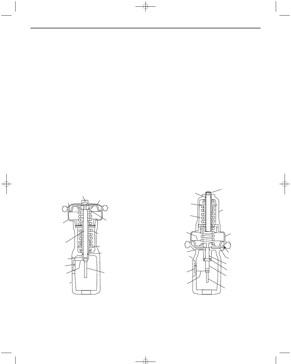
Air-to-Lower - Termination Nos. 220 thru 223, 240 thru 244,
Figure 1. In this type of actuator, air pressure moves the push rod
downward compressing the spring. In the event of air failure, the
push rod moves to its extreme upward position.
Air-to-Raise - Termination Nos. 230, 231, 233, 250 thru 254,
Figure 2. In this type of actuator, air pressure moves the push rod
upward compressing the spring. In the event of air failure, the
push rod moves to its extreme downward position.
Thus, by selection of actuator and control valve plug action,
either push-to-close or push-to-open, the control valve will either
open or close on failure of air pressure to diaphragm.
The spring and diaphragm are completely enclosed to protect
them from dust, dirt and other foreign matter. Spring adjustments
are made with a ball bearing spring adjustment sleeve.
Diaphragm and spring assembly may easily be removed for
replacement or substitution.
The construction and operating range are listed on the data plate
mounted on actuator. Actuator size and spring are selected to
meet the requirements of the application. In service the actuator
should create full travel of the valve plug when the pressure range
indicated on data plate is applied. This pressure range is most
generally 3 to 15 psi (20 to 100 kPa), but other ranges are avail-
able.
For precise control of valve plug position or where two valves are
to be operated in sequence by one control device, a W.E.
Anderson valve positioner, Catalog Number 100N or 165, is rec-
ommended.
O-Ring
Spring Seat
Range Spring
Push Plate
Assembly
Upper Diaphragm
Casing
1/4˝ NPT
Input Connection
Diaphragm
Lower Diaphragm
Casing
Push Rod
Range Spring
Adjusting Screw
Travel Indicator
Plate
Travel Indicator
Yoke
Valve Stem
Figure 1. Air-to-Lower Actuator
Range Spring
Adjusting Screw
Spring Casing
Diaphragm
Casing
1/4˝ NPT
Input Conn.
Diaphragm
O-Ring
Travel Stop
Collar
Push Rod
Valve Stem
Travel Indicator
Travel Indicator
Plate
Yoke
V-Packing
Push Plate
Range Spring
Spring Seat
O-Ring
Figure 2. Air-to-Raise Actuator
IB-5A103:IB-5A103 1/29/10 11:37 AM Page 3