Dwyer SC4151 User Manual
Love, Isoverter®ii, Love controls
949-0528-2
Page 1 of 4
June, 2000
IsoVerter®II
Models SC4130, SCL4130, SC4151 & SCL4151
INSTALLATION INSTRUCTIONS
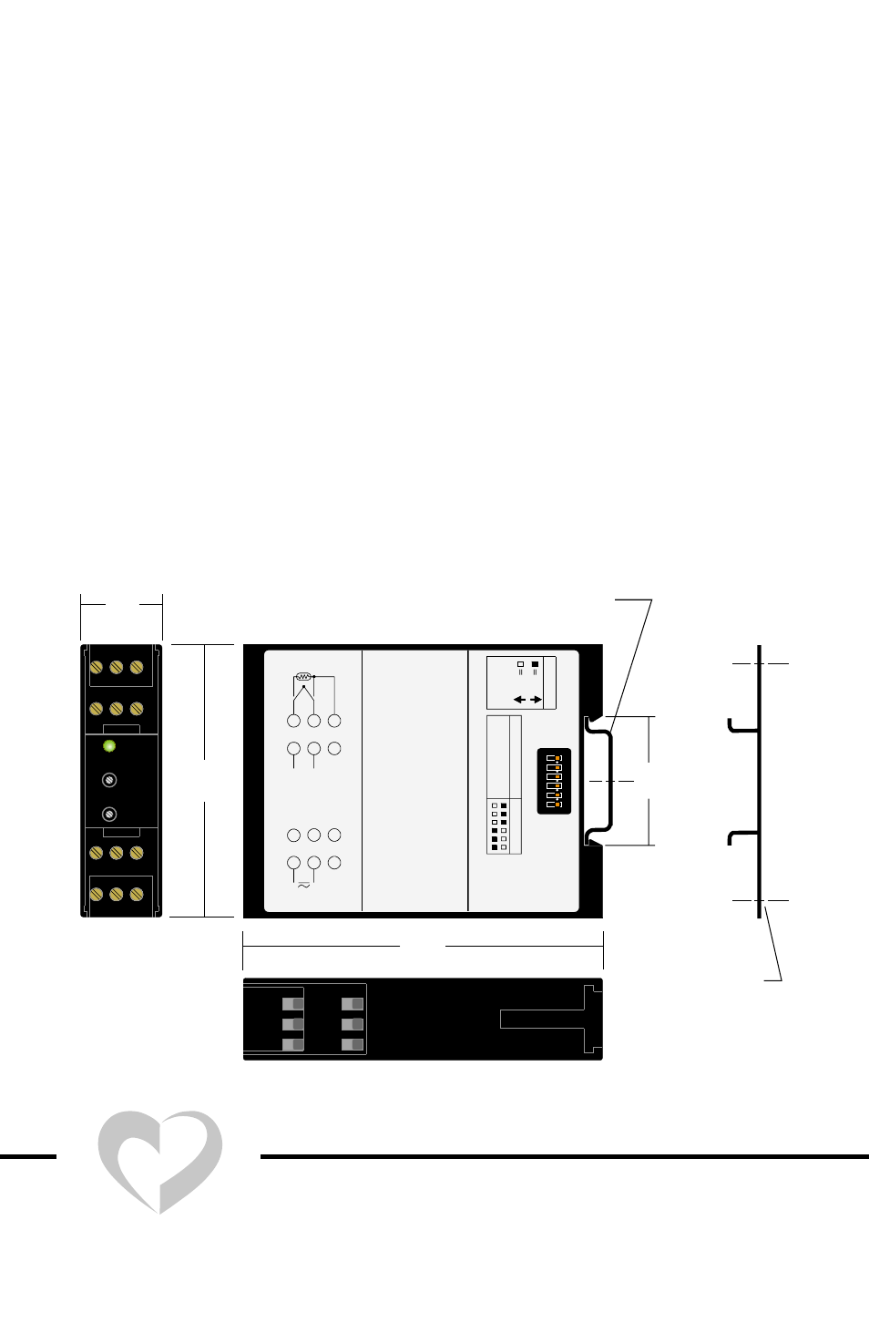
Dimensions
Getting Started
1.) Using a small screwdriver, ball point pen, etc. set the Output Switch
(SW-1) on the side of the unit (see Output Programming on page 2).
2.) Mount unit into panel. (see Mounting on page 2).
3.) Connect unit to input signal, output signal, and power wiring (see Wir-
ing on page 3).
4.) Check calibration (See Calibration on page 3).
Specifications are on page 4.
DIN EN 50022-35
(not supplied)
ADAPTER BRACKET
FOR SURFACE
MOUNTING (OPTIONAL)
KIT#: 1007-35DINADPTR
(1.40)
35.5
(0.886)
22.5
(2.950)
75
(3.880)
98.5
7
10
8
11
9
12
123456
ON
MICHIGAN
C
ITY,
IN
46361,
U.S.A.
DIV.OF
DWYER
INSTRUMENTS,
INC.
LOVE
CONTROLS
OUTPUT
INPUT
_
6
3
+
ISO-VERTER
®®
II
INPUT
RANGE:
S/N:
MODEL:
+
5
4
2
1
_
POWER
10
9
8
7
11
12
MADE
IN
U.S.A.
290-2886
OUTPUT
RANGE
SW1
NOT
BLANK
==
APPLICABLE
CURRENT
4-20
mA
VOLTAGE
0-10
V
OFF
ON
KEY
1
2
34
5
6
Dimensions in
millimeters (inches)
POWER
SPAN
ZERO
a Division of Dwyer Instruments, Incorporated
PO Box 338 Michigan City, IN 46361-0338
(800) 828-4588 (219) 879-8000 FAX (219) 872-9057
www.love-controls.com
❍
❍
❍
LOVE CONTROLS
®
LOVE