Dwyer instruments, inc, Models and ranges – Dwyer UV User Manual
Page 2
OPERATION AND MAINTENANCE
Once installed, the Series UV In-Line Polysulfone
Flowmeter is self-operating and requires no maintenance
other than an occasional cleaning with mild soap and a
bottle brush. For this purpose, the unit has been designed
so that its body can be removed quickly and easily while
leaving all fittings intact.
When removing float for cleaning, note the floats “up” posi-
tion. The float is a precision part and must be reassembled
without adverse treatment, i.e. dropping, denting, and sur-
face abrasion.
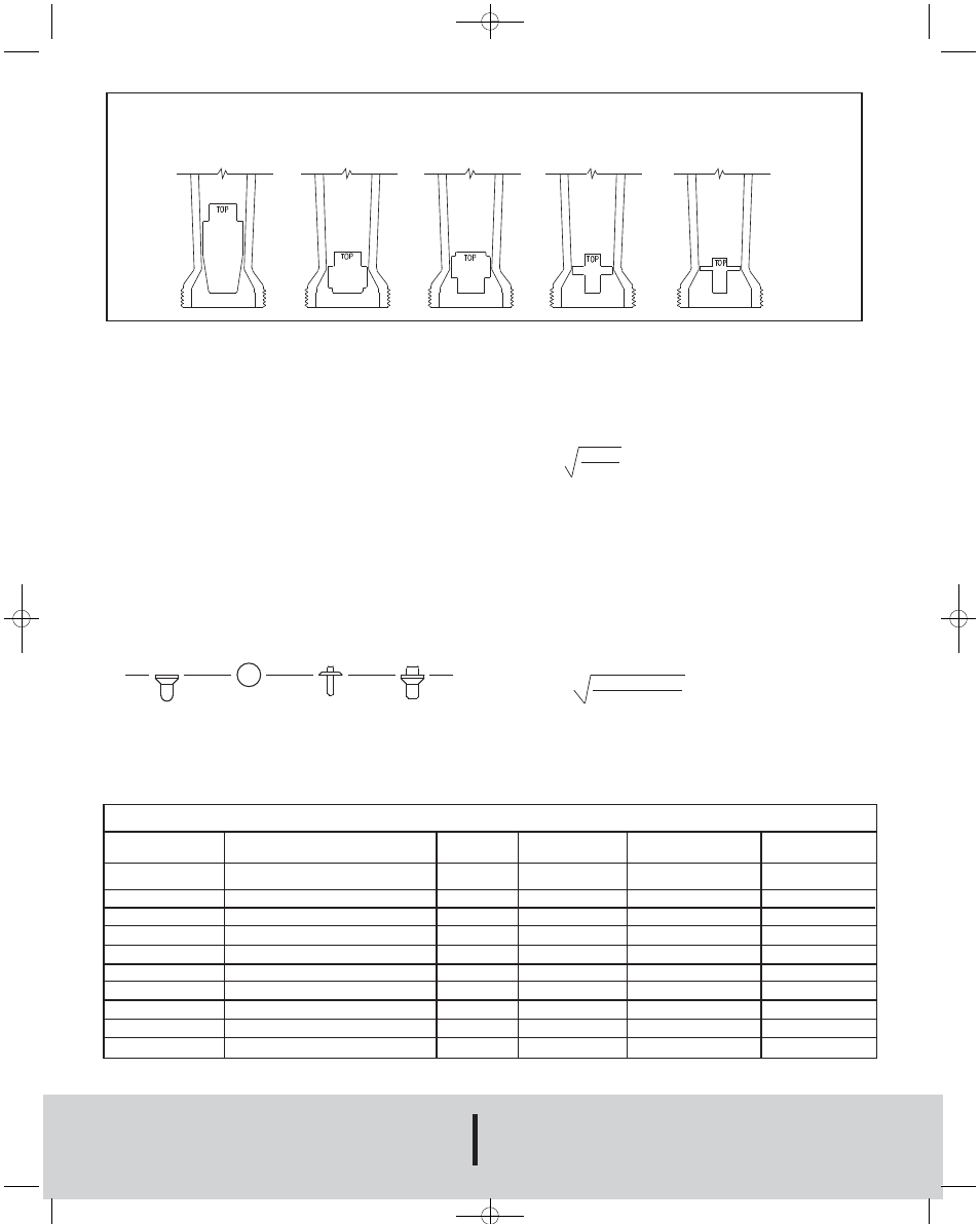
The standard technique for reading a Variable Area Flowmeter is
to locate the highest point of greatest diameter on the float, and
then align that with the theoretical center of the scale graduation.
In the event that the float is not aligned with a grad, an extrapo-
lation of the float location must be made by the operator as to its
location between the two closest grads. The following are some
sample floats shown with reference to the proper location to read
the float.
Variable Area Flowmeters used for gases are typically labeled with
the prefix “S” or “N”, which represents “Standard” for English units
or “Normal” for metric units. Use of this prefix designates that the
flowmeter is calibrated to operate at a specific set of conditions,
and deviation from those standard conditions will require correc-
tion for the calibration to be valid. In practice, the reading taken
from the flowmeter scale must be corrected back to standard
conditions to be used with the scale units. The correct location to
measure the actual pressure and temperature is at the exit of the
flowmeter, except under vacuum applications where they should
be measured at the flowmeter inlet. The equation to correct for
nonstandard operating conditions is as follows:
Q
2
= Q
1
x P
1
x T
2
P
2
x T
1
Where:
Q
1
= Actual or Observed Flowmeter Reading
Q
2
= Standard Flow Corrected for Pressure and
Temperature
P
1
= Actual Pressure (14.7 psia + Gage Pressure)
P
2
= Standard Pressure (14.7 psia, which is 0 psig)
T
1
= Actual Temperature (460 R + Temp °F)
T
2
= Standard Temperature (530 R, which is 70°F)
Example: A flowmeter with a scale of 10-100 SCFH Air. The float
is sitting at the 60 grad on the flowmeter scale. Actual Pressure is
measured at the exit of the meter as 5 psig. Actual Temperature
is measured at the exit of the meter as 85°F.
Q
2
= 60.0 x (14.7 + 5) x 530
14.7 x (460 + 85)
Q
2
= 68.5 SCFH Air
©Copyright 2009 Dwyer Instruments, Inc.
Printed in U.S.A. 7/09
FR# 443147-00 Rev. 6
DWYER INSTRUMENTS, INC.
Phone: 219/879-8000
www.dwyer-inst.com
P.O. BOX 373 • MICHIGAN CITY, IN 46361, U.S.A.
Fax: 219/872-9057
e-mail: [email protected]
Model Number
UV-0112
UV-1112
UV-2112
UV-3112
UV-4112
UV-5112
UV-A112
UV-B112
UV-C112
UV-D112
Body
Polysulfone
Polysulfone
Polysulfone
Polysulfone
Polysulfone
Polysulfone
Polysulfone
Polysulfone
Polysulfone
Polysulfone
Fitting Material
Polysulfone
Polysulfone
Polysulfone
Polysulfone
Polysulfone
Polysulfone
Polysulfone
Polysulfone
Polysulfone
Polysulfone
Float
Virgin PTFE
Virgin PTFE
Virgin PTFE
Virgin PTFE
Virgin PTFE
Virgin PTFE
Virgin PTFE
Virgin PTFE
Virgin PTFE
Virgin PTFE
Models and Ranges
2-20 GPM
3-30 GPM
4-40 GPM
14-100 SCFM
1-10 GPM
.5-5 GPM
2.5-28 SCFM
.25-2.5 GPM
1-13 SCFM
Range
0.25-2.5 GPM (1-9.5 LPM)
0.5-5.0 GPM (2-19 LPM)
1.0-10.0 GPM (4-38 LPM)
2.0-20.00 GPM (8-76 LPM)
3.0-30.00 GPM (12-112 LPM)
4.0-40.00 GPM (20-150 LPM)
1-13 SCFM (30-370 LPM)
2.5-28 SCFM (70-780 LPM)
5-50 SCFM (70-1400 LPM)
14-100 SCFM (400-2800 LPM)
Medium
Water
Water
Water
Water
Water
Water
Air
Air
Air
Air
5-50 SCFM
F-60:Series UV Bulletin 7/24/09 10:01 AM Page 2