Dwyer instruments, inc, Caution – Dwyer VFB User Manual
Page 2
the boot. Pipe up inlet and discharge using pipe thread sealant tape or
pipe thread sealant to insure against leakage.
Surface Mounting on Piping Only: An alternate method of surface
mounting is by omitting the mounting screws and supporting the Visi-
Float
®
Flowmeter on the connecting piping only. For this method extra
long or straight pipe threads should be used so that nuts may be run onto
the pipe and later tightened against the back of the panel to retain the
unit in proper position. Use the appropriate hole layout information from
Figure 1, but omit the small holes.
Mounting on Piping Only Without Panel: For the temporary or
laboratory type installation, the panel may be omitted altogether and the
flowmeter installed directly in rigid piping. Its light weight permits this
without difficulty.
OPERATION
To start system, open the valve slowly to avoid possible damage. Control
valves on BV and SSV models are turned clockwise to reduce flow,
counter clockwise to increase flow (valve is designed for flow adjustment
only, not intended to be used as an open/shut-off valve). A nylon insert is
provided in the threaded section of the valve stem to give a firm touch to
the valve and to prevent change of setting due to vibration.
The performance of low range units used in air or gas applications may
be affected by static electricity. Excessive static charge may cause the
ball float to behave erratically or provide a false reading. To ensure the
proper function of the unit, the application should be designed to
minimize or dispel static electricity.
The standard technique for reading a Variable Area Flowmeter is to
locate the highest point of greatest diameter on the float, and then align
that with the theoretical center of the scale graduation. In the event that
the float is not aligned with a grad, an extrapolation of the float location
must be made by the operator as to its location between the two closest
grads. The following are some sample floats shown with reference to the
proper location to read the float.
Variable Area Flowmeters used for gases are typically labeled with the
prefix “S” or “N”, which represents “Standard” for English units or
“Normal” for metric units. Use of this prefix designates that the flowmeter
is calibrated to operate at a specific set of conditions, and deviation from
those standard conditions will require correction for the calibration to be
valid. In practice, the reading taken from the flowmeter scale must be
corrected back to standard conditions to be used with the scale units.
The correct location to measure the actual pressure and temperature is
at the exit of the flowmeter, except under vacuum applications where
they should be measured at the flowmeter inlet. The equation to correct
for nonstandard operating conditions is as follows:
Q
2
= Q
1
x P
1
x T
2
P
2
x T
1
Where:
Q
1
= Actual or Observed Flowmeter Reading
Q
2
= Standard Flow Corrected for Pressure and
Temperature
P
1
= Actual Pressure (14.7 psia + Gage Pressure)
P
2
= Standard Pressure (14.7 psia, which is 0 psig)
T
1
= Actual Temperature (460 R + Temp °F)
T
2
= Standard Temperature (530 R, which is 70°F)
Example: A flowmeter with a scale of 10-100 SCFH Air. The float is sitting
at the 60 grad on the flowmeter scale. Actual Pressure is measured at
the exit of the meter as 5 psig. Actual Temperature is measured at the
exit of the meter as 85°F.
Q
2
= 60.0 x (14.7 + 5) x 530
14.7 x (460 + 85)
Q
2
= 68.5 SCFH Air
MAINTENANCE
The only maintenance normally required is occasional cleaning to assure
reliable operation and good float visibility.
Disassembly: The flowmeter can be disassembled for cleaning by
simply disconnecting the piping, dismounting the unit from the panel and
removing the top-plug-ball stop. Take out the ball or float by inverting the
body and allowing the float to fall into your hand. (Note: It is best to cover
the discharge port to avoid losing the float through that opening.) When
removing the float guide assembly on VFB models 85 and 86, be careful
not to lose the short pieces of plastic tubing on both ends of the guide
which serve as float stops.
Cleaning: The flow tube and flowmeter body can best be cleaned with a
little pure soap and water. Use of a bottle brush or other soft brush will
aid the cleaning. Avoid benzene, acetone, carbon tetrachloride, alkaline
detergents, caustic soda, liquid soaps (which may contain chlorinated
solvents), etc. and avoid prolonged immersion.
Reassembly: Reinstall the float, remount, connect and place the unit
back in service. A little stop cock grease or petroleum jelly on the “O”rings
will help maintain a good seal as well as facilitate assembly. No other
special care is required.
For VFB models 85 and 86, first install the lower fitting, next the float
guide and float and finally the upper fitting and plug. Be certain that both
ends of the float guide are properly engaged and the float is correctly
oriented.
ADDITIONAL INFORMATION
For additional flowmeter application information, conversion curves,
factors and other data covering the entire line of Dwyer Instruments, Inc.
full-line catalog.
Do not completely unscrew valve stem unless flowmeter is
unpressurized and drained of any liquid. Removal while in service
will allow gas or liquid to flow out front of valve body and could
result in serious personal injury. For applications involving high
pressure and/or toxic gases or fluids, special non-removable
valves are available on special order. Contact factory for details.
CAUTION
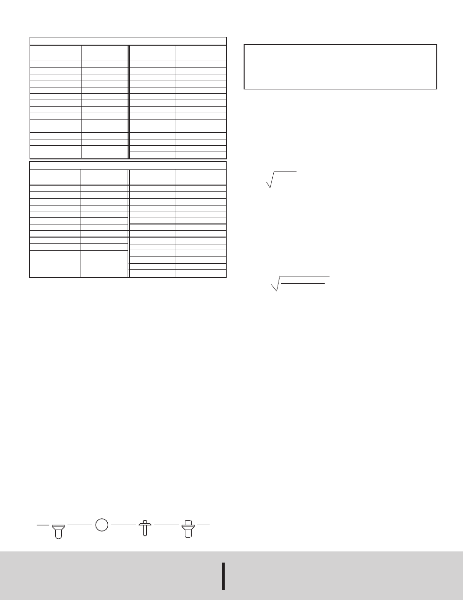
Model VFA — 2" Scale
Range
SCFH Air
.1-1
.2-2
.6-5
1-10
2-20
4-30
5-50
10-100
20-200
CC Water
per min.
6-50
10-100
20-200
Range
No.
1
2
3
4
5
6
7
8
9
32
33
34
Range
LPM Air
.06-0.5
.15-1
.6-5
1-10
3-25
6-50
10-100
Gal. Water
per hour
.6-5
1.2-10
3-20
8-40
Range
No.
21
22
23
24
25
26
27
41
42
43
44
Model VFB — 4" Scale
Range
SCFH Air
.3-3
1-10
2-20
4-40
10-100
15-150
20-200
SCFM Air
.3-3
CC/Min. Air
100-1000
Range
No.
50
91
51
52
53
54
55
90
60
LPM Air
.2-4
1-10
1-20
3-30
4-40
CC/Min. Water
2-30
GPH Water
.5-12
1-20
6-60
GPM Water
.2-2
.5-5
Range
No.
65
66
67
68
69
82
80
83
81
85
86
POPULAR RANGES
©Copyright 2013 Dwyer Instruments, Inc.
Printed in U.S.A. 6/13
FR# 52-440241-00 Rev.6
DWYER INSTRUMENTS, INC.
Phone: 219/879-8000
www.dwyer-inst.com
P.O. BOX 373 • MICHIGAN CITY, IN 46360, U.S.A.
Fax: 219/872-9057
e-mail: [email protected]