Dwyer instruments,inc, Specifications, Switch ratings maximum resistive load – Dwyer P4 User Manual
Page 2: Maintenance
Product must be maintained and installed in strict accordance with the
National Electrical Code and Dwyer product catalog and instruction
bulletin. Failure to observe this warning could result in serious injuries
or damages.
For hazardous area applications involving such things as (but not
limited to) ignitable mixtures, combustible dust and flammable materials,
use an appropriate explosion-proof enclosure or intrinsically safe
interface device.
The pressure and temperature limitations shown on the individual
catalog pages and drawings for the specified flow switches must not
be exceeded. These pressures and temperatures take into
consideration possible system surge pressures/temperatures and
their frequencies.
Selection of materials for compatibility with the media is critical to the
life and operation of Dwyer products. Take care in the proper selection
of materials of construction, particularly wetted materials.
DWYER INSTRUMENTS,INC.
P.O.BOX 373 MICHIGAN CITY, INDIANA 46361, U.S.A.
Phone: 219/879-8000
www.dwyer-inst.com
Fax: 219/872-9057
e-mail: [email protected]
Lit-By Fax: 888/891-4963
Important Points!
Life expectancy of switch contacts varies with applications. Contact
Dwyer if life cycle testing is required.
Ambient temperature changes do affect switch set points, since the
specific gravity of a liquid can vary with temperature.
Dwyer Products have been designed to resist shock and vibration;
however, shock and vibration should be minimized.
Filter liquid media containing particulate and/or debris to ensure the
proper operation of our products.
Electrical entries and mounting points in an enclosed tank may
require liquid/vapor sealing.
Dwyer Products must not be field-repaired.
Physical damage sustained by the product may render it
unserviceable.
MAINTENANCE/REPAIR
Regular maintenance of the total system is recommended to assure sustained optimum performance. These devices are not field repairable and
should be returned to the factory if recalibration or other service is required. After first obtaining a Returned Goods Authorization (RGA) number,
send the unit freight prepaid to the following. Please include a clear description of the problem plus any application information available.
Dwyer Instruments, Inc.
Attn: Repair Department
102 Highway 212
Michigan City, IN 46360
Specifications . . .
Wetted Materials
Housing and Piston
O-Ring
Spring
Other Wetted Parts
Operating Pressure, Maximum
Operating Temperature
Set Point Accuracy
Set Point Differential
Switch, See "Switch Ratings"
Inlet / Outlet Ports
Electrical Termination SPST
Electrical Termination SPDT
Ryton
®
- R4
Viton
®
316 Stainless Steel
Epoxy
250 PSIG @ 70°F
0°F to 225°F (-17°C to +107°C)
±15% Maximum
20% Maximum
SPST or SPDT, 20 VA
9/16" - 18 UNF - 2B Thread
No. 18 AWG, 24"L. Sarlink Zipcord Lead Wires
No. 18 AWG, 24" L., PVC Lead Wires
Switch Ratings
Maximum Resistive Load
Volts
0 - 30
120
240
Amps AC
.4
.17
.08
Amps DC
.3
.13
.06
VA
20
Note
The switch mechanism is an hermetically-sealed
reed switch for pilot duty only. Refer to electrical
data above or consult Factory.
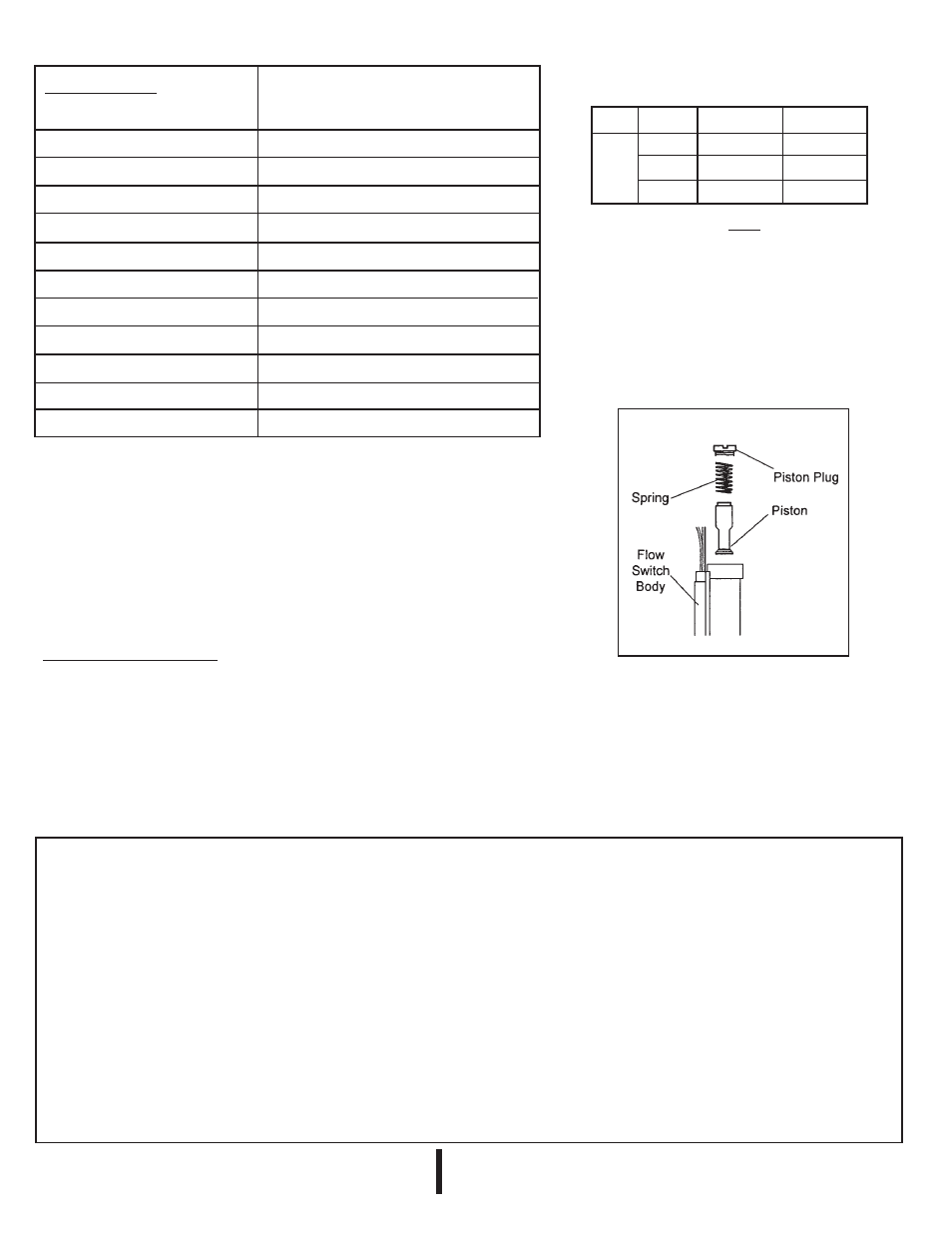
Maintenance . . .
The only maintenance normally required
is occasional cleaning when excessive contamination is present in the liquid.
To disassemble the flow switch for cleaning: With system shut down and no liquid in
piping, remove: 1) Piston Plug 2) Spring
3) Piston
It is not necessary to remove the unit from the system. Reassemble unit in reverse order;
i.e., #3 - #1 above. Use care when handling spring to prevent distortion.