Dwyer SFI-100T User Manual
Page 2
©Copyright 2010 Dwyer Instruments, Inc.
Printed in U.S.A. 2/10
FR# 83-443327-00 Rev. 1
MAINTENANCE
With all mechanical type sensing units, a minimal amount of
cleaning is required. However if a 150-micron filter is used,
reduced cleaning can be expected.
However, because Dwyer Instuments, Inc. utilizes a patented
sensing design, no magnets are molded inside the impeller, to
attract ferrous material. This greatly reduces the necessary
maintenance when used in mechanical systems with ferrous
residuals. If residuals are found inside the unit, clean with mild
detergent. Inspect for impeller wear. If impeller vibration is
noticeable, or if the unit produces an oscillation (whirring or
buzzing) sound, replace the impeller.
A-711T SENSOR OPTION INSTALLATION
This procedure is for customers who purchased an SFI-100T
Sight Flow Indicator and want to replace the A-711T Sensor.
1. Orient the sight flow indicator with the “belly” down. The sen-
sor “pocket” should be in the 9 o’clock position (as one is facing
the unit).
2. Position the A-711T sensor with the wire cable leads at 6
o’clock and the exposed sensor portion at 9 o’clock.
3. Firmly and evenly press the sensor onto the back of the sight
flow indicator. The assembly will only go on one way.
4. Place bracket over the A-711T and line up the screw holes in
the bracket with the holes in the back of the SFI-100T body.
Screw in the provided mounting screws with the provided lock
washer going in between the bracket and the screw head.
5. Follow electrical installation for lead termination.
ELECTRICAL INSTALLATION (for A-711T Option Only)
1. Connect the RED wire from the sensor to the positive 8 to 28
VDC power supply output.
2. Connect the BLACK wire from the sensor to the negative or
ground connection of the power supply output.
3. Connect the WHITE wire to get a 5 VDC digital pulse where
the frequency of the pulse is proportional to the flow rate.
4. Connect the GREEN wire to get an 8 to 28 VDC pulse where
the frequency of the pulse is proportional to the flow rate. The
voltage level will be equal to the supply voltage (on the RED
wire) minus approximately 0.7 volts.
CAUTION: DO NOT Connect the white and green leads togeth-
er. Any unused output connections should remain disconnected.
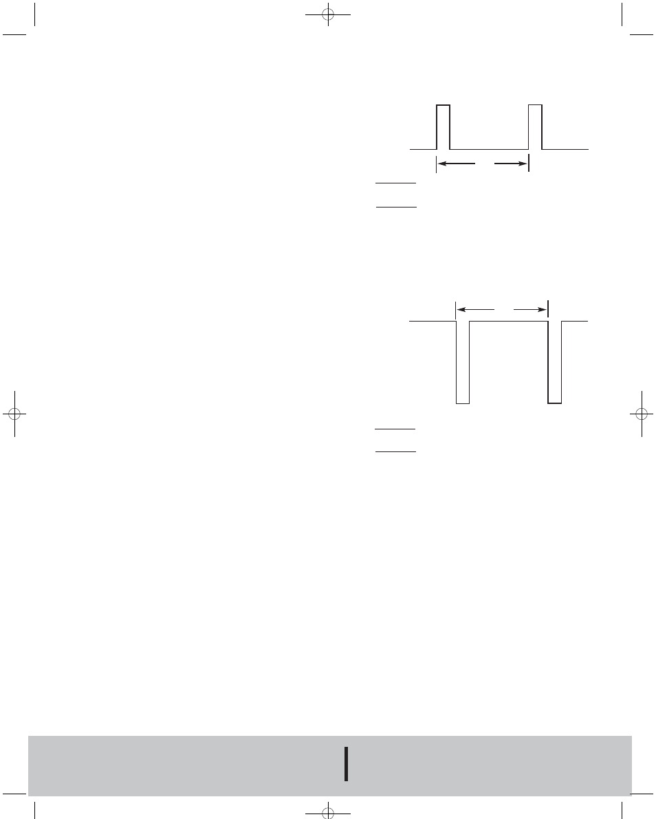
OUTPUT SIGNALS (for units with A-711T Option)
White Wire Connection:
5 Volts
0 Volts
Green Wire Connection:
8 - 28 Volts
0 Volts
ƒ
GPM = Freq (Hz)
for SFI-100T-1/2˝-A711T
2.0
ƒ
W.E. ANDERSON DIV., DWYER INSTRUMENTS, INC.
P.O. BOX 358 • MICHIGAN CITY, INDIANA 46361 U.S.A.
Phone: 219/879-8000
www.dwyer-inst.com
Fax: 219/872-9057
e-mail: [email protected]
GPM = Freq (Hz)
for SFI-100T-3/4˝-A711T
1.5
GPM = Freq (Hz)
for SFI-100T-1/2˝-A711T
2.0
GPM = Freq (Hz)
for SFI-100T-3/4˝-A711T
1.5
F-40:SFI-100T 1/29/10 9:51 AM Page 2