Connections, Specifications – Dwyer LOFM User Manual
Page 2
The LOFM Electromagnetic Flow Sensor is designed for low-flow
chemical injection or difficult-to-meter applications with pulsat-
ing metering pumps in 3/4” to 1/4” pipe/tube. The housing is
made of sturdy splashproof HDPE plastic.
With no moving parts, the LOFM can handle fluids contain-
ing particulate matter without clogging or jamming, keeping
maintenance at a minimum. With no metallic parts (100%
PVDF body and PVDF carbon fiber-filled electrodes), the me-
ter is corrosion-resistant and compatible with a wide range of
chemicals. Accuracy is maintained with conductive fluids (>20
microSiemens) of varying viscosities and densities.
The LOFM meter is compact enough to fit most pump/injection
systems. With zero straight pipe required after an elbow, it can
be easily mounted in tight spaces. The mounting bracket adds
stability.
The LOFM meter has optocoupled current sinking or current
sourcing pulse output that can be connected to the Dwyer’s
RTI rate/total display or a 4 to 20 mA loop for powering analog
devices. Outputs and power are provided through a cable with
8-pin female circular connector.
gEnEraL inFOrMatiOn, FEatUrES and SPEciFicatiOnS
FEatUrES
inStaLLatiOn and cOnnEctiOnS
inStaLLatiOn
Positioning.
The LOFM can be mounted vertically or horizon-
tally. It is important to choose a position that will ensure full
pipe. (Under certain conditions of empty or partially-full pipe
the meter may give a pulse out when there is no flow.) With a
zero straight pipe requirement after an elbow, the LOFM meter
can be installed in tight spaces.
Mounting.
The LOFM may be supported by its piping connec-
tions IF the piping is rigid. The meter and pipe must be per-
fectly aligned with no flexion at the fittings to prevent damage
to the meter and leakage. It is highly recommended to use the
mounting bracket provided. The mounting bracket uses two #8
screws on a 1.5” center.
Piping.
Metal pipe, metal tube, or plastic tubing can be used
with the meter. The standard FlareTek® fittings can be used
with or without NPT adapters on 3/4” or 3/8” pipe. If used, NPT
adapters should be hand-tightened onto the fittings to avoid
damage to internal O-ring seals. Thoroughly clean the pipe
threads and nose and apply Teflon tape to adapter threads.
Hold fittings/adapters with a wrench while tightening the pipe
to prevent damage to the meter. If using FlareTek® fittings, fol-
low the installation instructions provided with your flare tool.
Power Supply.
A 12 VDC linear, regulated power supply with an
output current of at least 0.25 A is recommended. If a switch-
ing power supply must be used, consult Seametrics for ap-
proved manufacturer’s model numbers.
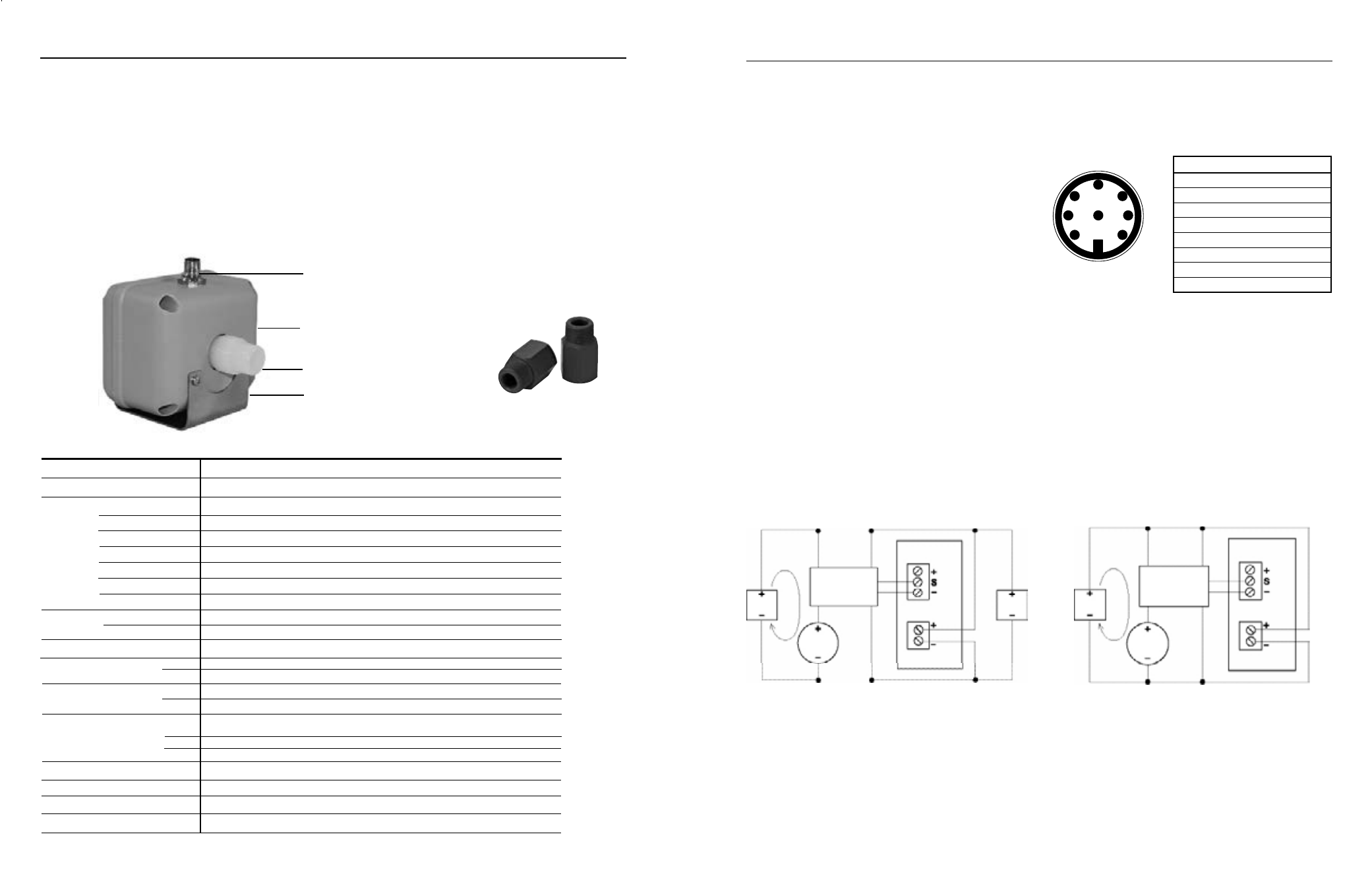
cOnnEctiOnS
Power and signal connections are provided through the 8-pin
male bulkhead connector on the meter housing (20’ (6m)
cable provided). See the Pin Assignment and Connections
diagrams below.
In addition, it is necessary for proper operation to ground the
unit to a good quality earth ground. Assure negative power
supply is grounded to earth and to the entire electrical/me-
chanical system. If metal piping is used, jumper inlet and
outlet pipes together and connect to ground for best results
in metering accuracy.
2
1
3
7
4
6
5
8
Sensor Input
rti
Power
1
LOFM
4-20 ma Device and rti with Single Power Supply
Dual Power Supply with Loop isolation
Pin# Function color
1
Pulse (-)
White
2
Ground
Brown
3
Pulse (+)
Green
4
4-20 (+)
Yellow
5
Not Used
Grey
6
Not Used
Pink
7
4-20 (-)
Blue
8
Power (+)
Red
Sturdy HDPE housing
8-pin circular bulkhead connector, 20’ (6 m) cable provided
FlareTek® fittings
are standard
Threaded NPT adapters
can be purchased separately
(available in PVC or PVDF)
Internals made of chemical and corrosion-resistant PVDF
Mounting bracket
3/4”, 1/2”, 3/8”, 1/4”**
FlareTek® fittings standard in 3/4” or 3/8” flowbody; NPT threaded adapters also available
PVDF
PVDF carbon fiber-filled
PVDF carbon fiber-filled
HDPE with glass fiber
PVDF
PVC or PVDF
EPDM or Fluoroelestomer
0˚ to 130˚ F (-18˚ to 54˚ C)
32˚ to 200˚ F (0˚ to 93˚ C)
150 psi
20 GPM Max. (0.2 GPM cut off)
3 GPM Max. (0.03 GPM cut off)
+/- 1%, +/- 0.005 GPM of reading across rated range
+/- 1%, +/- 0.002 GPM of reading across rated range
Optocoupled current sinking or current sourcing pulse output: 30 Vdc, 5 mA max;
4 to 20 mA current loop: 7 Vdc plus load voltage drop min; 50 Vdc max
PE102-075: 500 pulses/liter (1892 pulses/gallon),
PE102-038: 1,000 pulses/liter (3785 pulses/gallon).
10-15 Vdc, 150 mA (linear power supply recommended)
>20 microSiemens
Hardware/software, conductivity-based
NEMA 4X (IP 66)
Pipe Size
Fittings
Materials Body
Electrodes
ground
Housing
Fittings (Flaretek®)
adapters (nPt)
O-rings (for nPt)
temperature ambient
Fluid
Pressure
Flow range
-1
-2
accuracy
-1
-2
Output Signal
-1
-2
Power
conductivity
Empty Pipe Detection
Environmental
SPEciFicatiOnS*
*Specifications subject to change
**Requires adaptors
FlareTek® is a registered trademark of Entegris, Inc.
12-15
Vdc
4-20
device
4-20 mA
loop
2
3
4
8
7
rti
LOFM
12-24
Vdc
4-20
device
4-20 mA
loop
12-15
Vdc
Sensor Input
Power
1
2
3
4
8
7
cable Plug contact
arrangement
FlareTek® is a registered trademark of Entegris, Inc.