Dwyer instruments, inc – Dwyer CAM User Manual
Page 6
©Copyright 2009 Dwyer Instruments, Inc.
Printed in U.S.A. 9/09 FR# RA-443445-00 Rev. 2
DWYER INSTRUMENTS, INC.
Phone: 219/879-8000
www.dwyer-inst.com
P.O. Box 373 • Michigan City, IN 46361-0373, U.S.A.
Fax: 219/872-9057
e-mail: [email protected]
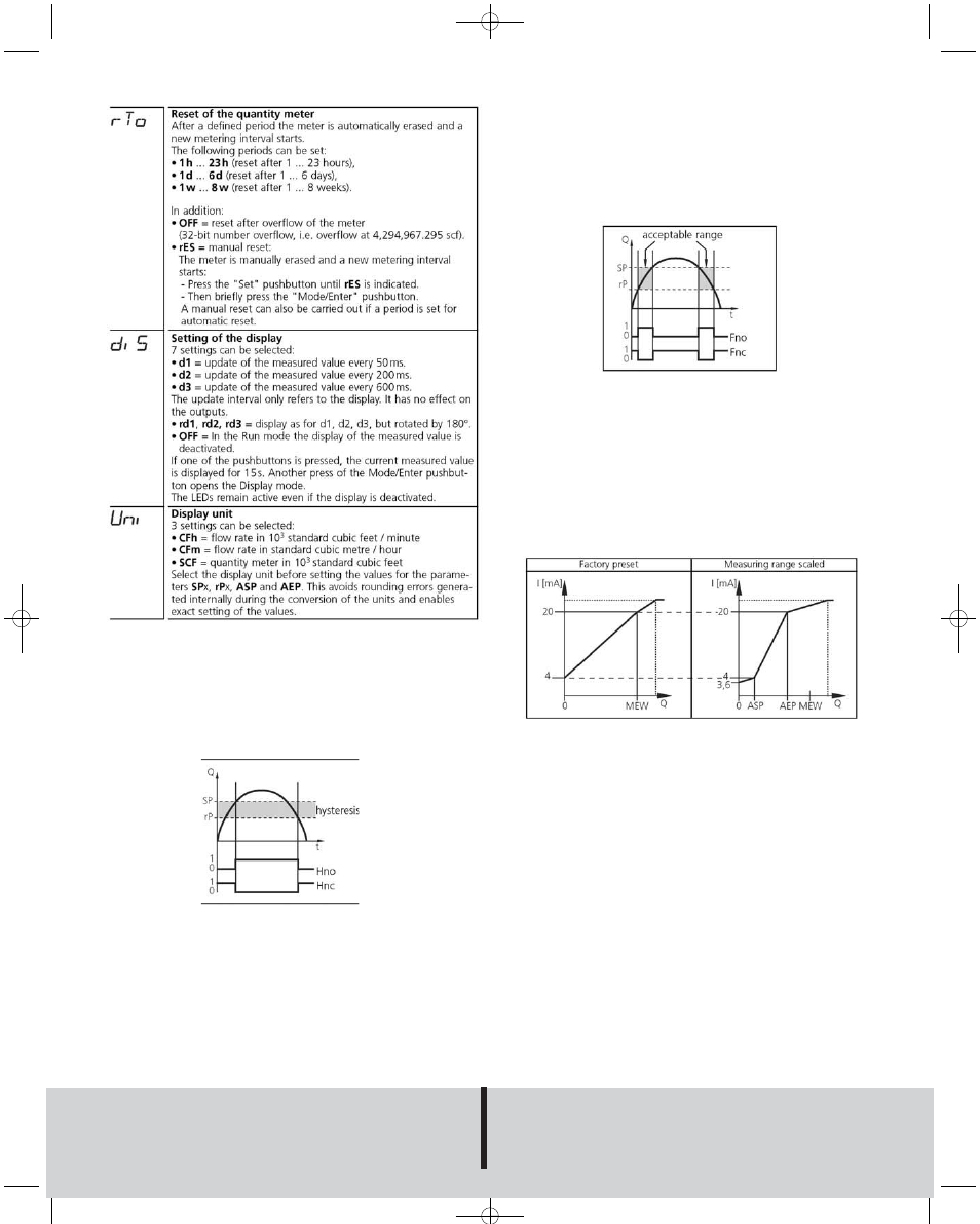
Hysteresis Function:
Keeps switching state of output stable if flow rate varies about preset
value. With flow rate rising, output switches when switch-on point has
been reached (SPx). With flow rate falling, output does not switch back
until switch-off point (rPx) has been reached. To adjust hysteresis: set
switch-on point, then set switch-off point at requested distance.
Window Function:
Enables monitoring of a defined acceptable range. When flow rate varies
between switch-on point (SPx) and switch-off point (rPx), output is
switched (window function/NO) or not switched (window function/NC).
Width of window can be set by means of the difference between SPx and
rPx. SPx=upper value, rPx=lower value.
Scaling measuring range (analog output):
Analog start point (ASP) is the measured value at which the output sig-
nal 4 mA is defined. Analog end point (AEP) is the measured value at
which the output signal 20 mA is defined. Minimum distance between
ASP and AEP = 25% of final measuring range value. Output signal
ranges from 4 to 20 mA in set measuring range. Output is also indicated
by: flow rate above measuring range (output signal > 20 mA), or flow rate
below measuring range (output signal between 3.6 and 4 mA).
Fault Indication
OL: Detection range exceeded (flow rate > 120% of final value of mea-
suring range)
SC 1: Flashing - short circuit in switching output 1*
SC 2: Flashing - short circuit in switching output 2*
SC: Flashing - short circuit in both switching output*
Err: Flashing - fault in measuring probe
*Concerned output is switched off as long as short circuit continues.
Faults are indicated even if display is deactivated.
Figure 7
Figure 5
Figure 6
Chart 3
C-32:Magnesense bulletin 9/24/09 11:48 AM Page 6