Dwyer instruments, inc – Dwyer DAFM User Manual
Page 2
©Copyright 2008 Dwyer Instruments, Inc.
Printed in U.S.A. 10/08
FR# R1-443660-00
DWYER INSTRUMENTS, INC.
Phone: 219/879-8000
www.dwyer-inst.com
P.O. BOX 373 • MICHIGAN CITY, INDIANA 46361, U.S.A.
Fax: 219/872-9057
e-mail: [email protected]
DAFM
DAFM
DAFM
4˝
12˝
20˝
24˝
AIR FLOW
Short Side Duct Dimension
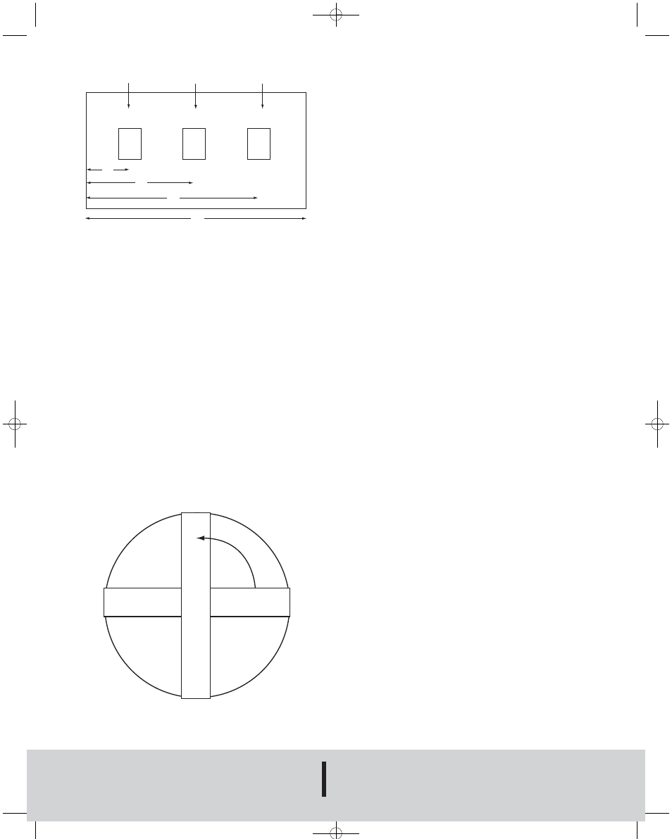
Figure 1: Top view illustration of probe placement example.
Note: Illustration not to scale.
Please note that all probes should be installed vertically and
running parallel to each other if installed in a rectangular duct.
RECTANGULAR DUCT PROBE INSTALLATION
1. Cut 4˝ X 1˝ holes at locations calculated above in side of duct.
2. Place silicon bead around holes.
3. Slide DAFM into holes and screw four self drilling screws into duct to
attach DAFM.
4. Connect 1/4˝ OD plastic tubing to barb fittings on DAFM.
5. Check all fittings and tubing connections for leaks using a leak
detector.
6. Tee all high and low ports into one high and one low line and connect
to transmitter or gage.
7. The devices should be checked once a year for build-up of dirt of
debris common in an HVAC system.
CIRCULAR DUCT MODELS
Determining Probe Number and Location for Round Ducts
1. Note that in round ducts only two probes are needed. The quantity of
probes needed does not depend on size of the duct.
2. Locate probes 90 degrees apart. See Figure 2 for an example.
Figure 2: Cross-sectional view of probe placement in a round duct.
DAFM
D
A
F
M
90°
ROUND DUCT PROBE INSTALLATION
1. Cut 4˝ X 1˝ holes at locations calculated above in side of duct.
2. Place silicon bead around holes.
3. Slide DAFM into holes and screw four self drilling screws into duct to
attach DAFM.
4. Connect 1/4˝ OD plastic tubing to barb fittings on DAFM.
5. Check all fittings and tubing connections for leaks using a leak
detector.
6. Tee all high and low ports into one high and one low line and connect
to transmitter or gage.
7. The devices should be checked once a year for build-up of dirt of
debris common in an HVAC system.
CALIBRATION
Sometimes field calibration may be required if the probe is installed in a bad
location i.e. immediately downstream of an elbow. In order to calibrate, you
must either perform a traverse of the duct or a sum of the air registers and
compare this with the DAFM output. Then, you must make the correction
to the effective area in the computer to make up for the error.
MAINTENANCE
Upon final installation, the device should be checked once a year for a build
up of dirt or debris that can be common in an HVAC system. Also check
the mounting stability once a year. Other than this no routine maintenance
is required. The DAFM model is not field serviceable and should be
returned if repair is needed (field repair should not be attempted and may
void warranty). Be sure to include a brief description of the problem plus
any relevant application notes. Contact customer service to receive a
return goods authorization number.
Long Duct Dimension
AV-2-DAFM:TEMPLATE 10/8/08 8:39 AM Page 2