Dwyer instruments, inc – Dwyer FAFM User Manual
Page 2
©Copyright 2008 Dwyer Instruments, Inc.
Printed in U.S.A. 9/08
FR# R1-443658-00
DWYER INSTRUMENTS, INC.
Phone: 219/879-8000
www.dwyer-inst.com
P.O. BOX 373 • MICHIGAN CITY, INDIANA 46361, U.S.A.
Fax: 219/872-9057
e-mail: [email protected]
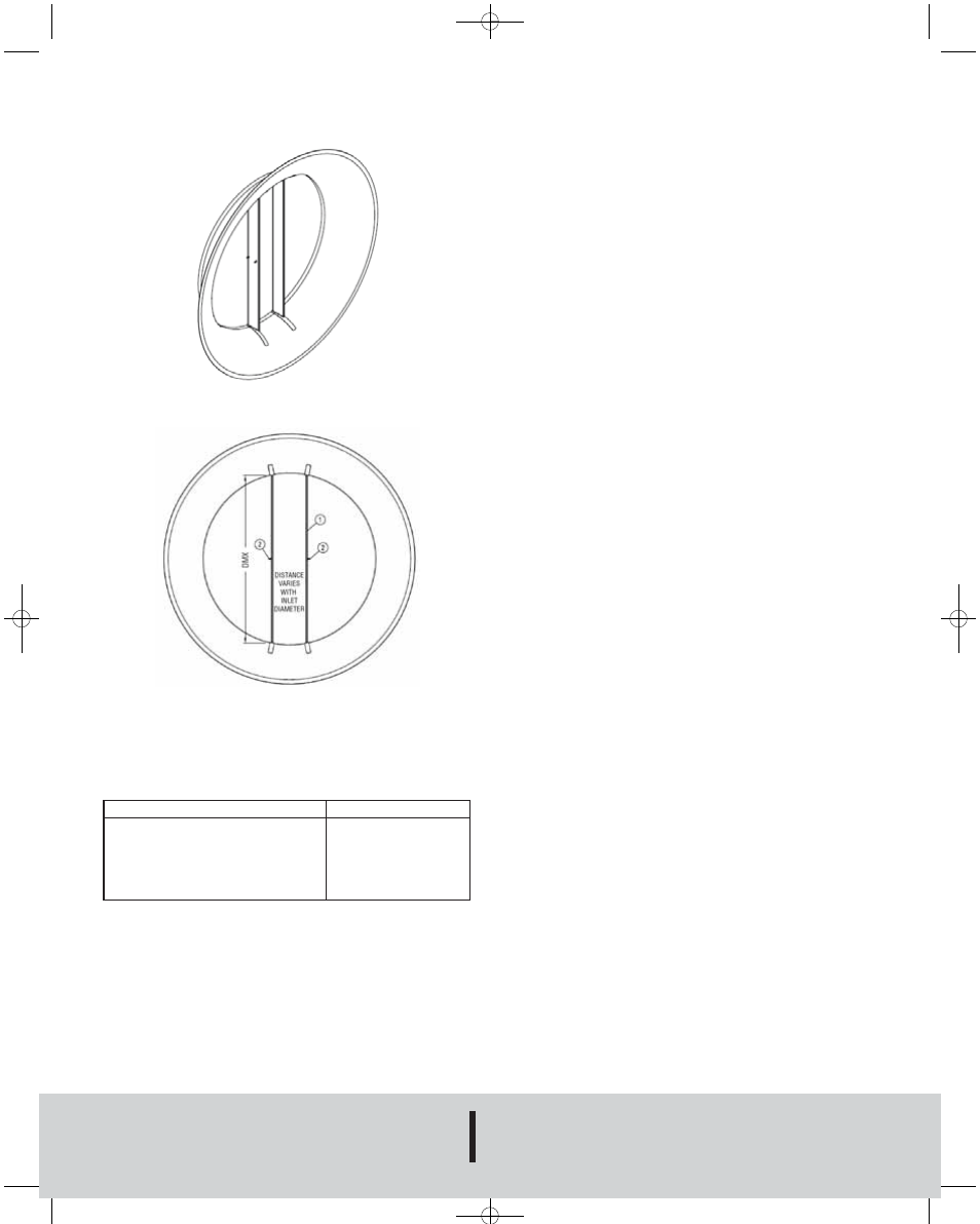
These units are meant to be installed running parallel to each other
as shown in figures 1 and 2.
Figure 1
To determine how far apart the two halves of the FAFM should be
placed, consult the chart below.
Figure 2
Fan Inlet Diameter
6"-9" (10.16 cm-22.86 cm)
10"-14" (25.4 cm-35.56 cm)
15"-20" (38.1 cm-50.8 cm)
21"-24" (53.34 cm-60.96 cm)
25" (63.5 cm) and up
Probe Separation
3" (7.62 cm)
4” (10.16 cm)
5" (12.7 cm)
6" (15.24 cm)
8” (20.32 cm)
To install the Model FAFM Fan Inlet Air Flow Measuring Probe
please refer to the following instructions:
1. Drill a minimum of two (2) holes into mounting plates.
2. Slide Model FAFM Fan Inlet Air Flow Measuring Probe Halves
into smallest diameter of the fan inlet.
3. Once in the smallest inlet diameter, push the probe to the
outside of the smallest inlet diameter and screw or rivet into
place using a minimum of two (2) screws or rivets per FAFM
half.
Note: The FAFM Air Flow Measurement Probe should be installed
with the holes in all probes visible from the outside of the fan.
4. Tee the two high and low connections to create one high and
one low output signal.
5. For double inlet fans tee all of the high and low connections to
create one high and one low output signal.
6. Connect the high and low outputs to a differential measurement
device such as a differential pressure transmitter.
CALIBRATION
Sometimes field calibration may be required if the probe is installed
in a bad location i.e. immediately downstream of an elbow. In order
to calibrate, you must either perform a traverse of the duct or a
sum of the air registers and compare this with the FAFM output.
Then, you must make the correction to the effective area in the
computer to make up for the error.
MAINTENANCE
Upon final installation, the device should be checked once a year
for a build up of dirt or debris that can be common in an HVAC
system. Also check the mounting stability once a year. Other than
this no routine maintenance is required. The FAFM model is not
field serviceable and should be returned if repair is needed (field
repair should not be attempted and may void warranty). Be sure
to include a brief description of the problem plus any relevant
application notes. Contact customer service to receive a return
goods authorization number.
AV-1-FAFM:TEMPLATE 9/11/08 9:51 AM Page 2