Dwyer instruments, inc – Dwyer 660 User Manual
Page 2
©Copyright 2009 Dwyer Instruments, Inc. Printed in U.S.A. 7/09 FR# 02-440751-00 Rev. 3
DWYER INSTRUMENTS, INC.
Phone: 219/879-8000
www.dwyer-inst.com
P.O. Box 373 • Michigan City, IN 46361-0373, U.S.A.
Fax: 219/872-9057
e-mail: [email protected]
CALIBRATION
1. Determine the velocity at which the HIGH (yellow) and LOW (red)
LEDs should be actuated. The NORMAL (green) LED will be on
when air flow is between the other two limits.
2. Use a suitable instrument to measure air velocity such as a
Model 480 Vaneometer
TM
or Model 471 Thermal Anemometer.
Take readings at 4-10 different locations within the open face area
to determine average velocity. This procedure will be performed
separately for high and low settings.
3. Allow 3-5 minutes warm-up time with no flow before adjusting
the 660 AVM.
4. HIGH setting. Vary blower speed or adjust sash position until
average velocity is at the upper limit required. Be sure air flow is
not obstructed. Turn HSP screw clockwise until LED’s change
from green to yellow.
5. LOW setting. Adjust flow until average velocity is at the lower
limit required. Turn LSP screw counter-clockwise until LED’s
change from green to red. Audible alarm will sound simultaneous-
ly. Press ACK. pad to silence.
6. Repeat adjustment of air velocity to HIGH and LOW flow rates
to confirm proper operation. Make further adjustments to 660
AVM settings if necessary.
7. To confirm proper operation of all alarms, press TEST pad.
MAINTENANCE
No routine maintenance is required for the 660 AVM. Use extreme
caution when cleaning the thermistor bead. The thin glass rod in
which it is housed is very fragile. Use only a soft camel hair brush
to gently remove accumulated dust. After cleaning or replacement
of fume hood filters or other fume hood service, it is recommend-
ed that you check AVM calibration following the procedure above.
The Model 660 Air Velocity Monitor is not field serviceable and
should be returned if repair is needed (field repair should not be
attempted and may void warranty). Be sure to include a brief
description of the problem plus any relevant application notes.
Contact customer service to receive a return goods authorization
number before shipping.
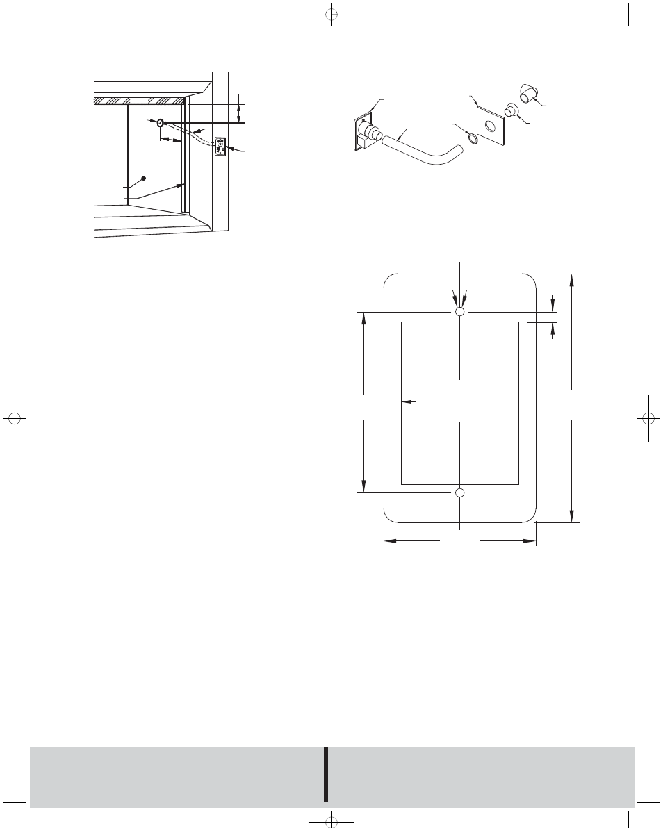
AIR VELOCITY
MONITOR
TUBING
SIDE WALL
SASH TRACK
SASH
OUTLET
HOLE
CENTER OF HOLE 4˝ (101)
BELOW BOTTOM OF
FULL OPEN SASH
4-10˝
(101 - 254)
600 AVM
FUME HOOD WALL
(Ø1.315˝)
TUBING
LOCKNUT
TUBE ADAPTER
OPTIONAL 90
°C
ELBOW ADAPTER
3.275
[83.2]
.187
[4.76]
4.5 REF.
[114.3]
DRILL TO 5/64 (2) FOR
PANEL MOUNTING
USE #6 SHEET
METAL SCREWS
DRILL TO 5/32 (4) FOR
JUNCTION BOX
MOUNTING USE 6-32
MACHINE SCREWS
2.125 X 2.938 (54 X 74.5)
CUTOUT FOR PANEL
MOUNTING
2.75 REF.
[70]
Fig. B
Fig. C
Fig. D
H-16:H-16 7/24/09 10:48 AM Page 2