Dwyer MS2-M User Manual
Page 3
Zero Calibration
The zero calibration can be set by applying zero pressure to both the pressure ports
and pressing the zero button for 3 seconds. If the local LCD is present, the display
will read Sero and then sequence back to the home display.
Span Calibration
The span calibration can be adjusted only after setting the zero adjustment. It must
be completed within 5 minutes of the last zero calibration. The span calibration
button will be ignored until the zero calibration is completed. Apply pressure to the
port of the transmitter that is associated with the maximum end of the transmitter
range. Press and hold the span button for 3 seconds. If the local LCD is present,
the display will read SPAn and then sequence back to the home display. If the span
calibration is attempted before adjusting the zero calibration, the FAIL error
message will flash on the display.
LCD Display
The Magnesense
®
II Differential Pressure Transmitter can be ordered with an
optional, integral LCD. If the display is not needed for normal operation, the
transmitter can be ordered without the LCD. A Model A-435-C field upgradeable
display is available. It comes with a housing cover with the overlay cut out for the
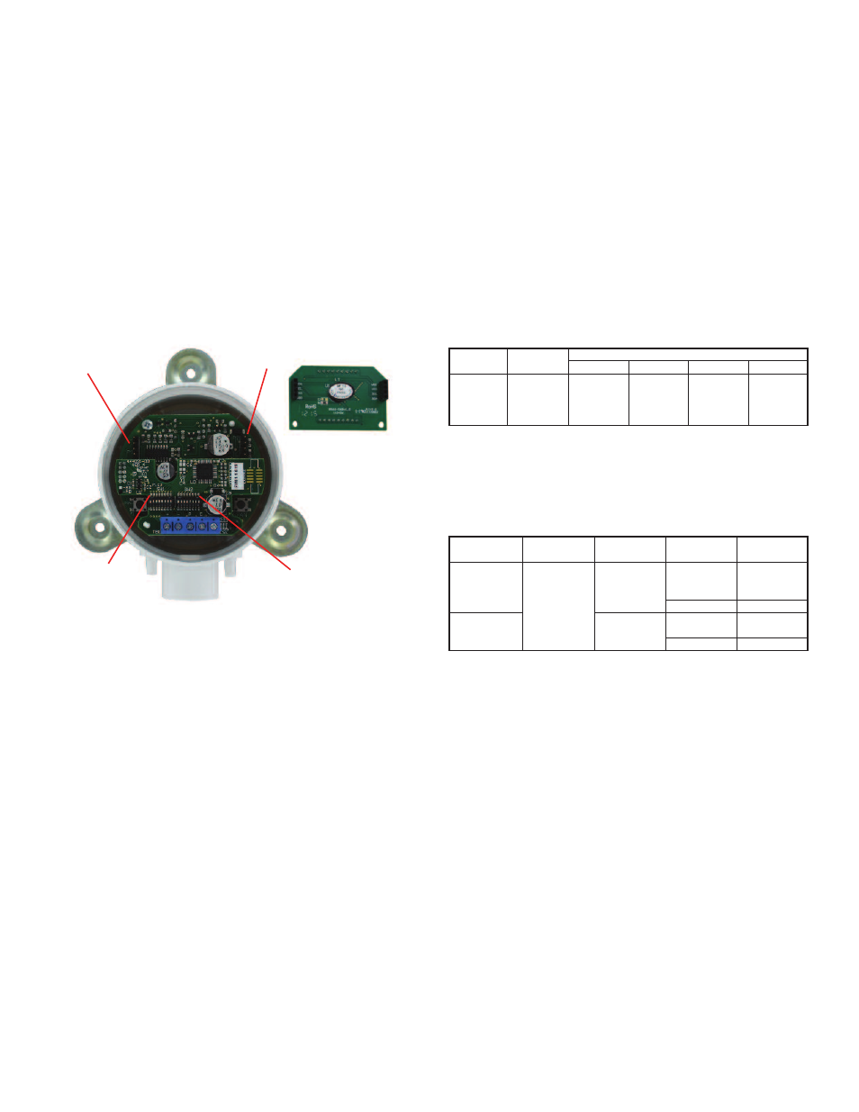
display. The display will plug into the pins as shown in Figure 5.
Display error Messages
ovEr = The applied pressure is greater than the maximum span value causing an
Over Range Error.
UndEr = The applied pressure is less than the minimum span value causing an
Under Range Error.
FAiL = When the span or zero buttons are pressed, the pressure value is out of the
range to allow a correct setting. This may be due to a sensor failure or incorrect
pressure being applied.
Err1 = The sensor is damaged.
PROGRaMMING MeNUS
Home Menu
During normal operation, the display will be in the Home Menu and will display the
current measured pressure and the engineering units.
Menu access Security
While in the Home Menu, press and hold the Zero and Span buttons
simultaneously until SECUr appears on the display in order to access the other
programming menus. Upon releasing the buttons, the display will indicate the
current security level.
If the current security level is the security level desired (i.e. Security Level 0), press
and hold the span button for three seconds to enter the Pressure, Velocity, or Air
Flow Menu.
If the security level is not the desired level, it can be changed temporarily to a lower
security level or permanently to a higher level of security by pressing the zero
button. A security code will be shown on the display and it can be changed to one
of the codes listed in the below table. The span button chooses which digit and the
zero button increments the value of that digit. Pressing and holding the span button
will store the value.
The level of access to the programming menus and the calibration is limited based
on the security level. The above table details the level of access for each security
level.
Programming Via Modbus
®
Communication Protocol
Supported Modbus
®
Communication Protocol Configurations
Intelligent Serial Configuration
Intelligent serial configuration enables the device to determine the baud rate, data
size, party, stop bits and even the Modbus
®
Communication Protocol mode directly
from the serial traffic. This allows the Series MS2 to be quickly and easily deployed
after a valid Modbus
®
Communication Protocol address is chosen.
To activate intelligent serial configuration, set a valid Modbus
®
Communication
Protocol address using the left DIP switch SW1, connect the serial bus and power
wires, and then apply power. The device will power up and begin examining the
serial bus for communication. The Red LED will repeatedly flash twice, indicating
that intelligent serial configuration is in progress.
If the device is setup offline or away from the main network, it is necessary to
generate Modbus
®
Communication Protocol traffic in order to configure the serial
communication. Attempting to read input registers is a good method to generate
Modbus
®
Communication Protocol traffic. Note that while serial configuration is in
progress, the device may not respond to requests. The device may require multiple
read requests to complete the serial configuration process.
The intelligent serial configuration process will complete once a message
addressed to the device is received and processed successfully. The serial
configuration parameters are then saved to non-volatile storage and loaded by
default each time the device starts. If the serial configuration of the bus changes, a
power cycle of the device is required to restart the Intelligent Serial Configuration
process.
figure 5
Security
Level
0
1
2
3
View Menu
Yes
Yes
No
No
Setting
000
111
222
333
edit Menu
Yes
No
No
No
Span
Yes
No
No
No
Zero
Yes
Yes
Yes
No
access
Modbus
®
Mode
RTU
ASCII
Data Size
8
7
Supported
Baud Rates
9600
19200
38400
57600
76800
115200
Parity
Even
Odd
None
1
None
Even
Odd
None
Stop Bits
1
2
1
2
DIP Switch
SW1
DIP Switch
SW2
1
The serial configuration, no parity with one stop bit is not officially supported by the Modbus
®
Communication Protocol standard. However, if this configuration is desired, set
switch 5 on DIP switch SW2 to off. The device will configure itself in Modbus
®
RTU Communication Protocol mode with a data size of 8, no parity, and 1 stop bit. The baud
rate will still be determined automatically.
LCD Pins
LCD Pins