Current output – Dwyer 629 User Manual
Page 3
ZERO
SPAN
13-30 VDC
(140 ma)
+
-
RECEIVER
mA
LED DISPLAY
POSITIVE SUPPLY
TERM
1 (+)
TERM 2 (-)
TERM 4 (+)
OPTIONAL LED DISPLAY
YELLOW
LED DISPLAY
CONNECTOR
PRESS AND
HOLD TO
ZERO THE
DISPLAY
PRESS TO DISPLAY
THE GAGE’S
PRESSURE RANGE
BE SURE TO TURN OFF POWER WHEN
CONNECTING OR REMOVING THE
DISPLAY’S CONNECTOR. FAILURE TO DO
SO CAN RESULT IN THE GAGE DAMAGE.
TRANSMITTER CONNECTION:
- TURN OFF POWER
- CONNECT THE POWER
SUPPLY AND RECEIVER TO
TERM 1 AND TERM 2 OF THE
GAGE AS SHOWN
- CONNECT POWER SUPPLY
(+) TO TERMINAL 4 (REQUIRED
FOR THE OPTIONAL DISPLAY ONLY)
- INSTALL THE DISPLAY’S CONNECTOR
- TURN ON POWER
POWER
SUPPLY
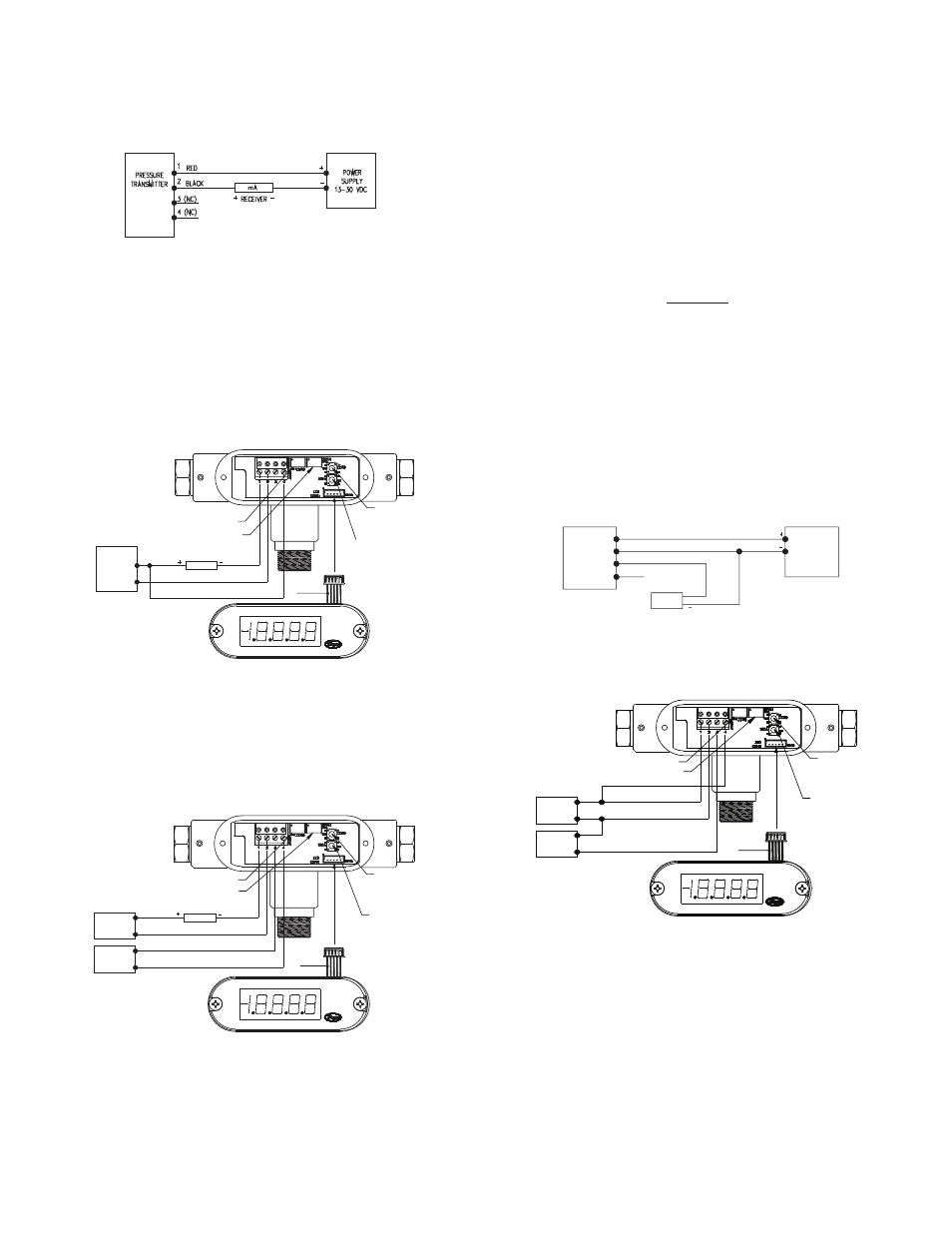
Fig. D: Current output with optional LED display
ZERO
SPAN
PRESS AND
HOLD TO
ZERO THE
DISPLAY
PRESS TO
DISPLAY THE
GAGE’S
PRESSURE
RANGE
OPTIONAL LED DISPLAY
13-30 VDC
(40 ma)
13-30 VDC
(100 ma)
POWER
SUPPLY
LED SUPPLY
POWER SUPPLY
+
+
-
-
TRANSMITTER CONNECTION:
- TURN OFF POWER
- CONNECT THE POWER SUPPLY
AND RECEIVER TO TERM 1 AND
TERM 2 OF THE GAGE AS SHOWN
OPTIONAL DISPLAY CONNECTION:
- CONNECT LED POWER SUPPLY
(-) TO TERMINAL 3
- CONNECT LED POWER SUPPLY
(+) TO TERMINAL 4
- INSTALL THE DISPLAY’S CONNECTOR
- TURN ON POWER
LED DISPLAY
CONNECTOR
YELLOW
BE SURE TO TURN OFF POWER WHEN
CONNECTING OR REMOVING THE
DISPLAY’S CONNECTOR. FAILURE TO DO
SO CAN RESULT IN THE GAGE DAMAGE.
TERM
1 (+)
TERM 4 (+)
TERM 3 (-)
TERM 2 (-)
RECEIVER
mA
LED DISPLAY
NEGATIVE SUPPLY
LED DISPLAY
POSITIVE SUPPLY
Fig. E: Current output with optional LED display using two power supplies
ELECTRICAL CONNECTIONS
Shielded cable is recommended for control loop wiring.
Electrical connections to the Series 629 pressure transmitters are made
to the terminal block located inside the housing. Remove the screws and
lift off the cover. Wire as shown in Fig. C, D or E. Use Fig. C for current
output connection. Use Fig. D for current output with optional LED
display. Use Fig. E for current output with optional LED display using two
power supplies. If ordering pre-wired cable, black wire is negative (-)
and red wire is positive (+).
Fig. C: Current output connection
Current Output
Fig. F: Voltage output connection
PRESSURE
TRANSMITTER
1 RED
2 BLACK (COMMON)
3 WHITE (+V OUT)
4 (NC)
RECEIVER
+V in
POWER
SUPPLY
13-30 VDC
ZERO
PRESS AND
HOLD TO
ZERO THE
DISPLAY
PRESS TO
DISPLAY THE
GAGE’S
PRESSURE
RANGE
LED DISPLAY
CONNECTOR
YELLOW
OPTIONAL LED DISPLAY
BE SURE TO TURN OFF POWER WHEN
CONNECTING OR REMOVING THE
DISPLAY’S CONNECTOR. FAILURE TO DO
SO CAN RESULT IN THE GAGE DAMAGE.
VOLTAGE OUTPUT
TRANSMITTER CONNECTION:
- TURN OFF POWER
- CONNECT POWER SUPPLY
(+) TO TERMINAL 1
- CONNECT POWER SUPPLY
(-) TO TERMINAL 2 AND
THE RECEIVER (-)
- CONNECT THE RECEIVER
(+) TO TERMINAL 3
- CONNECT LED POWER SUPPLY
(+) TO TERMINAL 4
- INSTALL THE DISPLAY’S CONNECTOR
- TURN ON POWER
POWER
SUPPLY
13-30 VDC
(140 ma)
RECEIVER
+
-
-
+ V OUT
LED DISPLAY
POSITIVE SUPPLY
TERM 4 (+)
TERM 1 (+)
TERM 2 (-)
TERM 3 (-)
SPAN
Fig. g: Voltage output with optional LED display
Wire Length - The maximum length of wire connecting transmitter and
receiver is a function of wire size and receiver resistance. Wiring should
not contribute to more than 10% of receiver resistance to total loop
resistance. For extremely long runs (over 1000 ft.), choose receivers
with higher resistance to minimize size and cost of connecting leads.
When the wiring length is under 100 feet, lead wire as small as 22 AWG
can be used.
Current (4-20 mA) Output Operation - An external power supply
delivering 13-30 VDC with minimum current capability of 40 mA DC (per
transmitter)is required to power the control loop. See Fig. C for
connection of the power supply, transmitter, and receiver. The range of
the appropriate receiver load resistance (R
L
) for the DC power supply
voltage available is expressed by the formula:
R
L
Max = Vps – 13
20 mA DC
VOLTAgE (0-5, 1-5, 0-10, 1-6 or 2-10 Volt) OUTPUT OPERATION
For voltage outputs, wire as shown in Fig. F or Fig. G. Use Fig. F for
voltage output connection. Use Fig. G for voltage output with optional
LED display. Terminal 1 is positive (+), terminal 2 is negative (-), terminal
3 is +Vout, terminal 4 is LED positive supply. If ordering optional pre-
wired cable, black wire is negative (-), red wire is positive (+) and white
wire is +Vout.
Voltage Output