Dwyer 629 User Manual
Page 2
INSTALLATION
1. Location: Select a location where the temperature of the unit will be
between 0°F and 175°F. Distance from the receiver is limited only by
total loop resistance (see electrical connections).The tubing feeding
pressure to the instrument can be practically any length required, but
long lengths will increase the response time slightly. Mount the
instrument in a location that will not be subject to excessive temperature,
shock or vibration.
2. Position: A vertical position is recommended (pressure connections
pointing horizontally) since that is how all standard models were
originally spanned and zeroed at the factory. They can be used at other
angles, but may require final spanning and zeroing. Due to potential
condensation build up that may travel down conduit or cable and into the
housing, it is recommended to install with the electrical conduit or cable
gland pointing downward.
3. Pressure Connection: Dual 1/4˝ female NPT pressure connections
are provided. Use pipe thread sealant tape or other suitable pipe joint
compound when making connection to the pressure source. Avoid
excess sealant which could block the pressure passage. When
monitoring liquid pressures, air trapped in the lines can cause incorrect
readings. Bleed fittings or similar mechanisms should be used to bleed
off any trapped air.
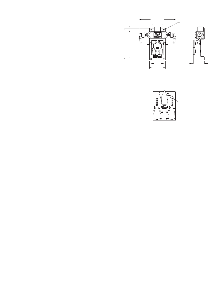
Optional 3-Way Valve
For applications where higher line pressures may be encountered at
installation or when it is necessary to remove the transmitter for
maintenance without interrupting the process, the optional three way
valve is recommended (See Fig. A).
Begin with valve V1 open and valves V2 and V3 closed (See Fig. B).
Slowly open valves V2 and V3. Once the pressure has stabilized and is
equal on the high and low side of the transmitter, valve V1 can be closed
and normal operation can proceed.
To ensure proper pressures will be detected by the 629 use the bleed
fitting provided with this package to free media of bubbles. Before
applying pressure to the process connections, turn V1 to the open
position and back off the bleed screw. Next apply pressure. After the
flowing liquid is free of bubbles, retighten the bleed screw.
Before removing the transmitter from operation, open valve V1 then
close valves V2 and V3.
Fig. A
Fig. B
9/32
[7.14]
6-29/32
[175.42]
2.400
[60.69]
5-7/16
[138.11]
6-1/64
[152.81]
3
[76.20]
2.400
[60.69]
2-1/16
[52.39]
Ø13/64 [5.64] DIA
MOUNTING HOLES
TYP 4 PLACES
B
BLEED SCREW