Ii controller from turning, Digihelic, Ii controller rs485 wiring – Dwyer DHII User Manual
Page 5
4
When wiring the instrument, you must follow industry standard practice for control and
protection against Electro-Static Discharge (ESD). Failure to exercise good ESD practices
may cause damage to the control.
WIRING
1. Remove cover.
2. To gain access to the wiring terminal blocks, remove the upper and lower screws toward the center
of the display board, and then flip the display board up at a 90° angle.
3. Wire to the two terminals blocks as shown in the wiring diagram.
Note: Depending on the application, it may be only necessary to wire to the smaller terminal block on
the upper board. In that case one of the liquid tight fittings may be removed and replaced with the
provided rubber plug.
4. For liquid tight applications, use only 1/2˝ liquid tight conduit.
5. When wiring is complete, reverse steps 2 and 1. Make sure the cover is properly tightened to the
housing.
INSTALLATION
Mount the instrument in a location that will not be subject to excessive temperature, shock or vibration.
Pressure Connections
Use 1/8 male NPT fittings. When tightening fittings, grasp the brass fitting on the Digihelic
®
II Controller
with a 1/2˝ wrench to prevent the fitting on the Digihelic
®
II Controller from turning.
ண
DIGIHELIC
®
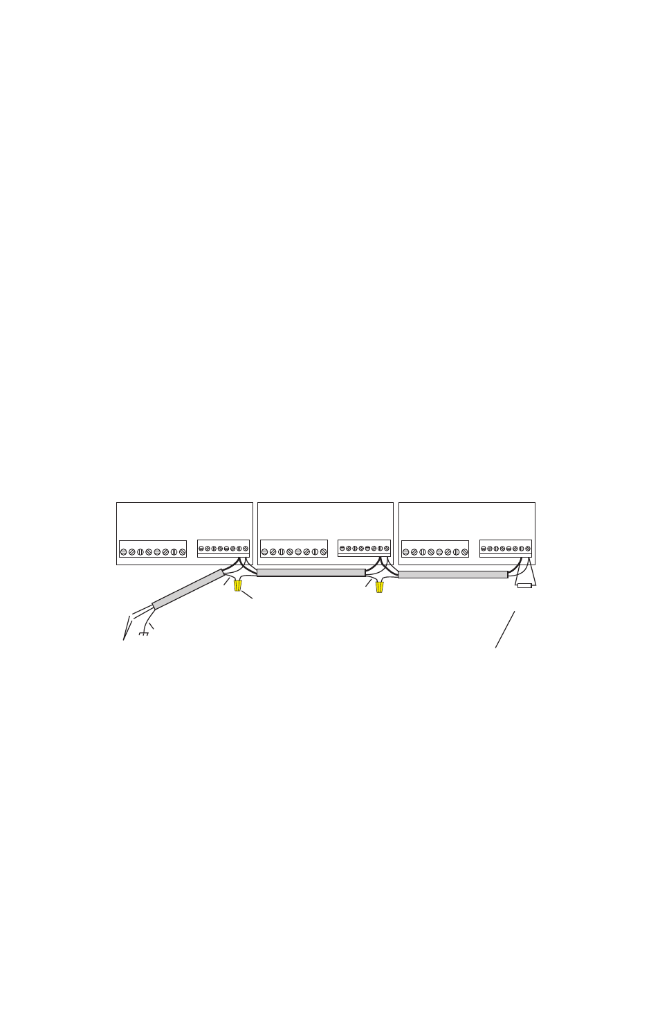
II CONTROLLER RS485 WIRING
SHIELD
SHIELD
SHIELD
SHIELD
TIE
TIE SHIELD
SHIELD TO
TO EARTH
EARTH GROUND
GROUND
TO
TO RS232
RS232 TO
TO
RS485
RS485 CONVERTER
CONVERTER
120
120 OHM
OHM
RESISTOR
RESISTOR
LAST
LAST UNIT
UNIT ON
ON RS485
RS485 BUSS
BUSS
WIRE
WIRE NUT
NUT
DIGIHELIC
DIGIHELIC
-- RS485
RS485 WIRING
WIRING TO
TO DAISY
DAISY CHAIN
CHAIN INSTRUMENTS
INSTRUMENTS
ON
ON THE
THE RS485
RS485 BUSS
BUSS
UP
UP TO
TO 128
128 UNITS
UNITS MAY
MAY BE
BE DAISY
DAISY CHAINED
CHAINED
THE
THE 120
120 OHM
OHM RESISTOR
RESISTOR
IS
IS USUALLY
USUALLY
ONLY
ONLY
NECESSARY
NECESSARY
FOR
FOR LONG
LONG
WIRE
WIRE RUNS.
RUNS.
1
1
2
2
3
3
4
4
5
5
6
6
7
7
8
8
1
1 2
2 3
3 4
4 5
5 6
6 7
7 8
8
CONNECTOR
CONNECTOR
ON
ON
LOWER
LOWER
BOARD
BOARD
CONNECTOR
CONNECTOR
ON
ON
UPPER
UPPER
BOARD
BOARD
1
1
2
2
3
3
4
4
5
5
6
6
7
7
8
8
1
1 2
2 3
3 4
4 5
5 6
6 7
7 8
8
CONNECTOR
CONNECTOR
ON
ON
LOWER
LOWER
BOARD
BOARD
CONNECTOR
CONNECTOR
ON
ON
UPPER
UPPER
BOARD
BOARD
1
1
2
2
3
3
4
4
5
5
6
6
7
7
8
8
1
1 2
2 3
3 4
4 5
5 6
6 7
7 8
8
CONNECTOR
CONNECTOR
ON
ON
LOWER
LOWER
BOARD
BOARD
CONNECTOR
CONNECTOR
ON
ON
UPPER
UPPER
BOARD
BOARD