Wiring – Dwyer DH User Manual
Page 4
3
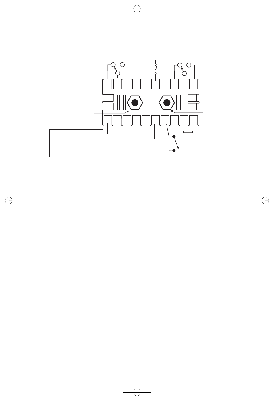
WIRING
20
20
19
19
18
18
17
17
16
16
15
15
14
14
13
13
11
11
12
12
10
10
9
8
7
6
5
4
3
2
1
21
21
22
22
23
23
24
24
C
C
N/C
N/C
N/C
N/C
N/O
N/O
N/O
N/O
SP1
RELAY
SP1
RELAY
SP2 OR
ALARM
RELAY
SP2 OR
ALARM
RELAY
3/8A 250VAC
MEDIUM LAG
3/8A 250VAC
MEDIUM LAG
100-240 VAC or
132-240 VDC POWER
100-240 VAC or
132-240 VDC POWER
NOTE1
NOTE1
A
B
_
+
RS485 SERIAL
COMMUNICATION
RS485 SERIAL
COMMUNICATION
_
+
24 VDC POWER
24 VDC POWER
REMOTE RESET
SWITCH
REMOTE RESET
SWITCH
NOTE 1
NOTE 1
4-20mA
transmitter
output
4-20mA
transmitter
output
Device receiving 4-20mA
signal. Check specifications
of this device for input load
resistance. Typical 250 to
600 OHMS, 900 OHMS
maximum
signal. Check specifications
of this device for input load
resistance. T
600 OHMS, 900 OHMS
maximum
_
_
+
+
_
+
High Pressure Port
High Pressure Port
Low
Pressure
Port
Low
Pressure
Port
NOTES:
1. The instrument may be powered from the AC line or 24 VDC. Do not wire AC
line terminals 4-5 and 24 VDC terminals 14-15 at the same time or damage to
the unit will result.
2. For supply connections, wire in accordance with an equivalent national standard
or code. Use copper conductors only rated for at least 75°C.
3. Terminals 11-15, 18 and 20 are rated CLASS 2.
4. ISOLATION:
Relays - 1500 VAC to all other inputs and outputs.
AC Line Power (terminals 4-5) - 1500 VAC to all other inputs and outputs.
RS485 output - 500 VAC to all other CLASS 2 wiring.
The 24 VDC Power, 4-20 mA transmitter, and Remote Reset Switch share
a common ground.
5. The Remote Reset Switch must be a dry contact switch.
6. Shielded cable is required for RS485 wiring.
WIRING
WARNING
If Digihelic
®
is powered by 24 VDC, the device receiving the 4-20 mA transmitter
output MUST NOT share a common ground with the 24 VDC supply or damage
to the Digihelic
®
will result.
ƽ
B-32:B-32 7/9/09 2:52 PM Page 4