Dwyer instruments, inc, Maintenance and service, Fig. e – Dwyer MP User Manual
Page 4: Fig. f
©Copyright 2009 Dwyer Instruments, Inc.
Printed in U.S.A. 9/09
FR# 14-443249-10 Rev.4
10. Dual Setpoint Manual Reset: Circuit style HH may
also be used for manual reset applications where it is
required to maintain contact on either relay following
pressure increase above its setpoint. Load or signal
connections are made to the appropriate terminals in
Section C (as in step 8). Connect terminals in Section
A through normally closed switches or pushbuttons as
shown in Fig. E. Use “dry-circuit” type switches such as
Dwyer Part No. A-601 with palladium, gold, etc. or
rotary wiping action type contacts is recommended.
Circuit style LL is used for manual reset applications
where it is required to maintain contact on either relay
following pressure decrease below the setpoint. Load
or signal connections are made to the appropriate ter-
minals in section C (as in step 8). A normally open type
manual reset switch such as Dwyer Part No. A-601 is
connected to the terminals in Section A. The circuit
must be “armed” by momentarily energizing the switch
while the pointer is to the right of the setpoint. From
that point on, the circuit will latch on pressure decrease
below the setpoint and remain latched on pressure
increase until manually reset with the optional switch.
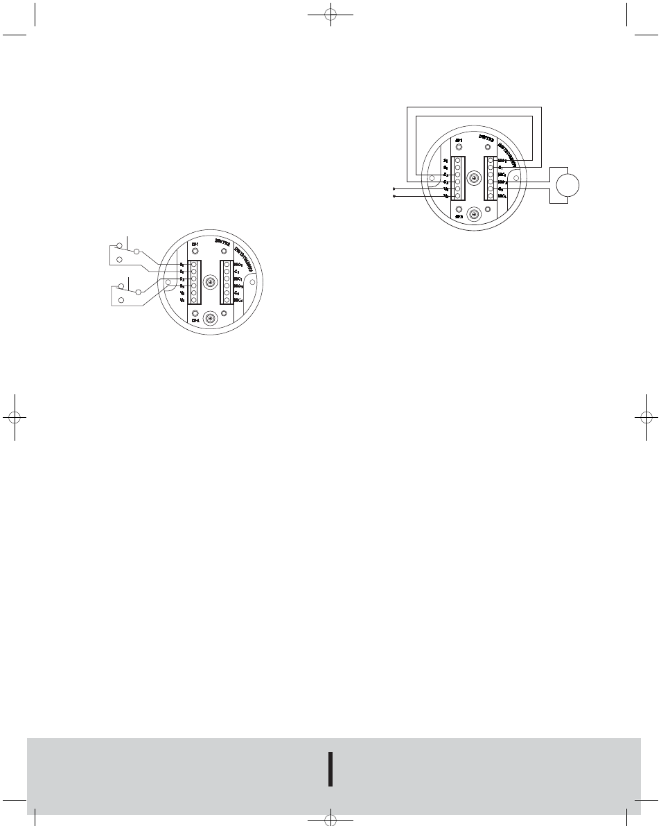
11. High Low Limit Control - Dual Setpoint: Standard
circuit style HH may be used to control various fans,
dampers, pumps, etc..., between the setpoints of a
Mini-Photohelic
®
Switch/Gage. To accomplish this, use
one setpoint relay to reset the other as shown in the
wiring diagram Fig. F. In this typical application, the
load would be connected to the N.C. contacts (NC2) of
the right setpoint relay SP2. The N.O. contacts of SP1
relay would be connected to the S2 reset terminals on
the rear of the instrument. On pressure rise to the right
setpoint relay SP2, the relay would pull-in and hold
even though the pressure might fall below that set-
point. If the pressure continued to fall to the left of set-
point SP1, then SP2 relay would be automatically DE-
ENERGIZED, returning to its normal position and in so
doing, open the reset terminal S2. The right setpoint
relay SP2 would thus be reset and the cycle could
repeat.
12. Dual Setpoint Special Purpose Circuits: Circuit
Style LL may be used where manual reset following
maintained contact on pressure decrease to either set-
point is required. Circuit HL and LH are combination
units. For special combinations of features and special
units consult factory.
13. Failure Mode: The Mini-Photohelic
®
circuit design pro-
vides certain protection in the event of a loss of electri-
cal power. Both relays will de-energize upon loss of
power.
MAINTENANCE AND SERVICE
Dwyer Mini-Photohelic
®
Switch/Gages are precision
instruments, expertly assembled and calibrated at the fac-
tory. They require no lubrication or periodic servicing. If
the interior is protected from dust, dirt, corrosive gases
and fluids, years of trouble-free service may be expected.
Zero adjustment should be checked and reset occasional-
ly to maintain accuracy.
Upon final installation of the Series MP Mini-Photohelic
®
Differential Pressure Switch/Gage and the companion
receiver, no routine maintenance is required. A periodic
check of the system calibration is recommended. The
Series MP is not field serviceable and should be returned
if repair is needed (field repair should not be attempted
and may void warranty). Be sure to include a brief descrip-
tion of the problem plus any relevant application notes.
Contact customer service to receive a return goods autho-
rization number before shipping.
RESET
NC
NO
NO
NC
RESET
+
–
Fig. E
24 VDC/VAC
LOAD
+
–
Fig. F
DWYER INSTRUMENTS, INC.
Phone: 219/879-8000
www.dwyer-inst.com
P.O. BOX 373 • MICHIGAN CITY, INDIANA 46361, U.S.A.
Fax: 219/872-9057
e-mail: [email protected]
B-37-A:B-37-A 9/29/09 9:37 PM Page 4