Dwyer MP User Manual
Page 3
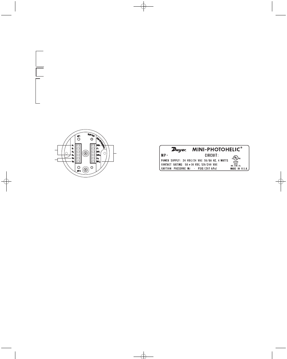
6. Electrical Connections: Refer to Fig. C for electrical
connections located on rear on Mini-Photohelic
®
Switch/Gage:
S1
→ SP1 Reset Terminal (Do not apply power)
S1
→ SP1 Reset Terminal (Do not apply power)
S2
→ SP2 Reset Terminal (Do not apply power)
S2
→ SP2 Reset Terminal (Do not apply power)
Vs
→ 24 VDC / 24 VAC 50/60 HZ
Vs
→ 24 VDC / 24 VAC 50/60 HZ
NO1
→ SP1 Relay N.O. Contact
C1
→ SP1 Relay Common Contact
NC1
→ SP1 Relay N.C. Contact
NO2
→ SP2 Relay N.O. Contact
C2
→ SP2 Relay Common Contact
NC2
→ SP2 Relay N.C. Contact
Section A contains external connections to the holding
circuit for manual reset applications. The function and
use of these connections varies somewhat depending on
the circuit style of the instrument. See steps 7 and 9 for
details.
Caution: Do not apply electrical current to
terminals in Section A.
Section B contains the power connections for the control
unit. Standard unit is designed to operate on 24 VDC / 24
VAC 50/60 HZ.
Caution: Do not apply 120 / 240 VAC to the power
connections.
Section C contains connections for SP1 and SP2 relays.
Connections are marked on the rear of the instrument.
7. Setpoint Calibration: Setpoint calibration is easily
attained by actuating the pushbuttons located on the
rear of the instrument. Pushbuttons are labeled SP1
and SP2. To set the setpoint SP1, apply pressure
where you require the SP1 relay to energize. Press
pushbutton marked SP1 on the rear of the instrument,
SP1 LED located on the front and rear of the instru-
ment will flash several times. When LED stops flash-
ing calibration is complete. Repeat the same steps
above for SP2 relay.
8. Circuit Style: The Mini-Photohelic
®
Switch/Gage is
available with several factory installed optional cir-
cuits. They are identified by the label shown in Fig. D.
This label is mounted on the upper side of the main
pressure housing.
The letter H denotes a circuit in which the relay can be
made to latch or remain energized after pressure
increases above its setpoint.
The letter L denotes a circuit in which the relay can be
made to latch or remain de-energized after pressure
decreases below its setpoint.
Two letters are required to fully identify a dual setpoint
unit. Thus, circuit style HH, which is standard, is a dual
setpoint circuit which has provisions for latching on
pressure increase to either setpoint. Circuit styles may
be used with either setpoint stated above.
9. Dual Setpoint Automatic Reset: Circuit style HH is
used for simple on-off switching applications. To place
in service, connect load circuits to the appropriate ter-
minals in Section C (Fig. C) for SP1 relay and SP2
relay. No connections are required in Section A.
SECTION A
SECTION B
SECTION C
+
–
Fig. C
Fig. D
Sectio
n
Sectio
n
Sectio
n
B-37-A:B-37-A 9/29/09 9:37 PM Page 3