Crystal GaugeCalXP Rebuild Kit User Manual
Page 3
GaugeCal
XP
Service Instruction Sheet
•
Page 3
C R Y S T A L
engineering corporation
12
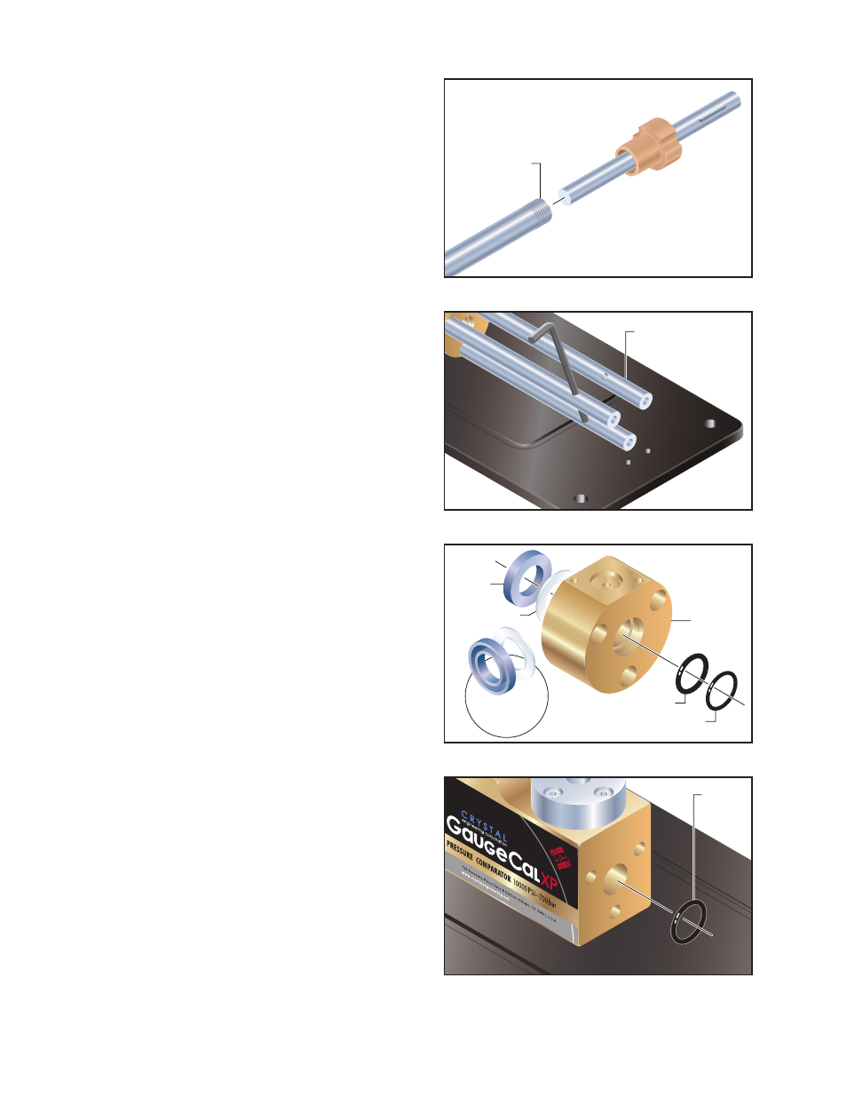
To remove the three (3) stainless steel Guide
Rods, insert the 4mm Allen key into the hole
in the side of each rod, and then pull to the
left (counter-clockwise) to loosen and un-
screw each one (figure 9).
When the final Guide Rod has been re-
moved, the Main Seal Block will fall away
from the Manifold Block.
13
From the front of the Main Seal Block,
remove the o-ring (
PN
3131) and the back-
up ring (
PN
3151) (figure 10).
14
From the rear of the Main Seal Block, remove
the Rod Seal (
PN
3152) and Rod Seal Backup
(
PN
3434) (figure 10).
Note:
When rebuilding the Main Seal Block
assembly, Dow Corning
®
111, or a similar
silicone-based lubricant, must be applied
to the grooved surface of the Rod Seal (
PN
3152).
When the Rod Seal is installed, its flat sur-
face should face toward the Main Seal Block,
while its grooved surface faces out to mate
with the Manifold Block (figure 10).
15
From the front of the Manifold Block,
remove the Main Seal Block o-ring (
PN
3418)
(figure 11).
Note:
When re-attaching the Main Seal
Block and Guide Rods to the Manifold Block,
you may find it easier to first remove the
Manifold Block from the Baseplate.
From the underside of the Baseplate, use a
4mm Allen key to remove the four (4) cap
screws holding the Manifold Block in place.
Use the three (3) Guide Rods to attach the
Main Seal Block to the Manifold Block, then
re-attach the Manifold Block to the Base-
plate before attaching the Piston Assembly
and Bearing Block.
Figure 8
Figure 9
Figure 10
Figure 11
Piston
Shaft
Guide Rod
Rod Seal and
Backup shown
rotated 90°
Rod Seal
(
PN
3152)
Rod Seal Backup
(
PN
3434)
Main Seal
Block
O-ring
(
PN
3131)
Backup ring
(
PN
3151)
O-ring
(
PN
3418)