Micro-flo, 0 installation 5.1 wiring connections, Circuit board – Blue-White Micro-Flo User Manual
Page 6: 3 flow verification output signal, 2 circuit board connections
MICRO-FLO
Page 6
5.0 Installation
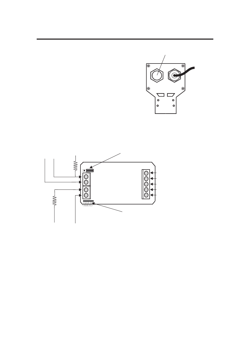
5.1 Wiring Connections
On sensor mounted units, the output signal
wires must be installed through the back panel
using a second liquid-tite connector (included).
To install the connector, remove the circular
knock-out. Trim the edge if required. Install the
extra liquid-tite connector.
On panel or wall mounted units, wiring may be
installed through the enclosure bottom or
through the back panel. See below.
KNOCK-OUT ½” diameter
Power Input
CIRCUIT
BOARD
Power input (+ 9 to 28 Vdc)
Power input ( ground )
Sensor input (+) RED
Sensor input (signal) BARE
Sensor input ( - ) BLACK
Programming disable jumper (un-installed).
Install on both pins to disable programming.
Front panel touch pad
ribbon cable connection
(+)
Rear view
(-)
Alarm output
Open Collector
30 VDC max
50mA max
Pulse output
Digital sq. Wave
5 VDC high
<.25 VDC low
50% duty cycle
5.3 Flow Verification Output Signal
When connected to external equipment such as a PLC, data logger, or Blue-
White metering pump, the pulse output signal can be used as a flow verification
signal. When used with Blue-White metering pumps, connect the positive (+)
terminal on the Micro-Flow circuit board to the pump’s yellow signal input wire
and the negative (-) terminal to the black input wire.
5.2 Circuit Board Connections
2K ohm
(+12 to 25 Vdc)
(-)
(+5 to 30 Vdc)
NPN
loop
5K ohm
NOTE: To reset the circuit board: 1) Disconnect power 2) Apply power while pressing the
two front panel buttons.