Micro-flo, 0 features, 0 model number matrix – Blue-White Micro-Flo User Manual
Page 3
2.0 Features
! Four connection options available:
1/8” F/NPT, 1/4” F/NPT, 1/4” OD x .170 ID Tubing & 3/8” OD x 1/4”
ID Tubing sizes.
! Six body size/flow range options available:
30 to 300 ml/min, 100 to 1000 ml/min, 200 to 2000 ml/min,
300 to 3000 ml/min, 500 to 5000 ml/min, 700 to 7000 ml/min.
! 3 model display variations:
FS = Sensor mounted display
FP = Panel mounted display (includes 6’ cable)
FV = No display. Sensor only. 5vdc current sinking output
! 6 digit LCD, up to 4 decimal positions.
! Displays both rate of flow and total accumulated flow.
! Open collector alarm setpoint.
! User selectable or custom programmable K-factor.
Flow units: Gallons, Liters, Ounces, milliliters
Time units: Minutes, Hours, Days
! Volumetric field calibration programming system.
! Non-volatile programming and accumulated flow memory.
! Total reset function can be disabled.
! Clear PVC viewing lens or PVDF chemical resistant lens.
! Weather resistant Valox PBT enclosure. NEMA 4X
Page 3
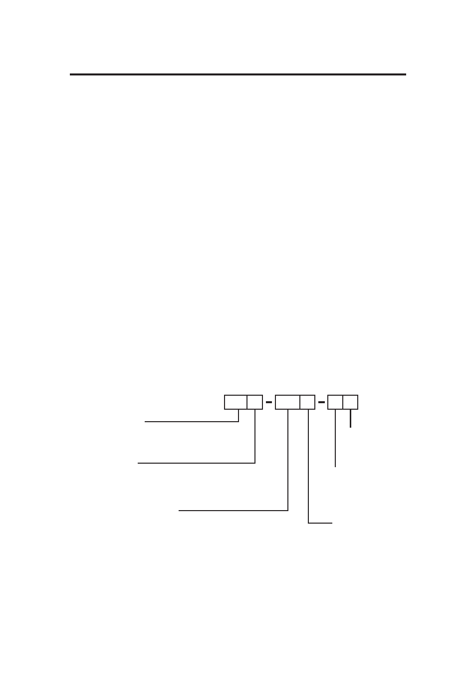
MICRO-FLO
METER FUNCTION
FS = Flow rate and Totalizing. On-sensor mounting
FP = Flow rate and Totalizing. Remote panel mounting
FV = Flow sensor only (no display)
POWER SUPPLY
1 = Transformer U.S. 115VAC/15VDC
2 = Transformer E.U. 220VAC/15VDC
3 = Transformer U.S. 230VAC/15VDC
None = No selection (customer supplied)
FLOW RANGE SELECTION
10 = 30-300 ml/min
20 = 100-1000 ml/min
30 = 200-2000 ml/min
40 = 300-3000 ml/min
50 = 500-5000 ml/min
60 = 700-7000 ml/min
O-RING SEAL
V = Viton
E = EPDM
CONNECTOR
4 = .250” OD tubing PVDF
5 = .125” Female NPT PVC
6 = .375” OD tubing PVDF
7 = .250” Female NPT PVC
LENS MATERIAL
0 = Clear PVC
1 = Opaque PVDF
3.0 Model number matrix