Installation instructions, single support, Installation instructions, double support – Badger Meter Ellipse Model PFA User Manual
Page 5
INSTALLATION INSTRUCTIONS, SINGLE SUPPORT
1 . Choose the proper location to install the PFA Fire Pump System Ellipse using AGA/ASME standards (or equivalent) . See
“Preso Ellipse Location Instructions” on page 7
2 . Grind the surface of the pipe where the PFA Fire Pump System Ellipse is to be inserted to provide a clean area for welding .
3 . Weld the supplied weld-o-let to the pipe using standard codes for your application (1/16" weld gap recommended) .
Take care to protect the threads during the welding process .
4 . Drill a hole through the pipe wall according to
.
5 . Deburr the hole just drilled, especially on the inside of the pipe .
Pipe Size
Model / Sensor
Weld Connector
Drill Bit
2…5 in .
PFA (1/2")
1/2"
5/8"
6…12 in .
PFA (7/8")
1"
1-1/8"
14…16 in .
PFA (1-1/4")
1-1/4"
1-3/8"
Table 2: Single support drill bit size
6 . Install the supplied compression fitting by threading it into the weld-o-let manually . Then with a wrench, tighten the
fitting another 1-1/4 turns, taking care not to tighten the compression nut .
7 . Install the instrument valves at the PFA Fire Pump System Ellipse head connections . Make sure the valves are FULLY
CLOSED to prevent them from leaking during startup .
8 . Insert the PFA Fire Pump System Ellipse through the compression fitting . See
. Carefully push the sensor by hand
further into the pipe until it reaches the opposite wall .
9 . While holding the PFA Fire Pump System Ellipse in its fully inserted position, align the arrow located on the sensor head
with the direction of flow . See
10 . Thoroughly tighten the compression nut in order to prevent leakage . After tightening the compression nut manually, turn
it another 1-1/4 turns with a wrench .
INSTALLATION INSTRUCTIONS, DOUBLE SUPPORT
1 . Follow steps 1 through 7 in
“Installation Instructions, Single Support”
. At 180° from and on the same plane as the previously
drilled hole, grind the surface of the pipe to provide a clean area for welding . Drill a hole and deburr, especially on the
inside of the pipe . The hole used for the double support should be sized according to
.
2 . Weld the double support weld-o-let making sure that it is centered with the drilled hole (1/16" weld gap recommended) .
3 . Install the PFA Fire Pump System Ellipse sensor through the two holes . Make sure that the double support pin passes
through the guide ring . See
.
4 . Align the arrow located on the sensor head in the direction of flow as in step 9,
“Installation Instructions, Single Support”
.
5 . Ensure that the PFA Fire Pump System Ellipse is in the correct orientation and spans the inside of the pipe . Tighten the
compression nut . After tightening the compression nut manually, tighten it 1-1/4 turns more using a wrench .
6 . Install the plug into the end of the double support weld-o-let . Tighten the plug to prevent leakage .
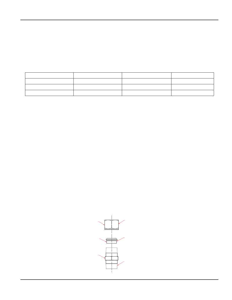
Threaded portion
to be installed
into weld fitting
on pipe
Install insert
as shown
Thread nut loosely
onto body of the
compression fitting
Body
Insert
Nut
Figure 4: Compression fitting assembly
User Manual
Page 5
April 2014