Installation instructions, double support – Badger Meter Model BHL User Manual
Page 6
8 . Install the instrument valves (optional) at the pressure connections on the BHL Ellipse sensor head . Make sure the valves
are FULLY CLOSED before proceeding .
9 . Open the isolating ball valve . Using a wrench, turn the threaded insertion rods clockwise into the pipe until the sensor
reaches the opposite pipe wall .
10 . Connect the instrument lines to the sensor head valves . Connect these lines to a gage or transmitter .
INSTALLATION INSTRUCTIONS, DOUBLE SUPPORT
OTEE:
N
For non-hot tap installations only .
1 . Follow steps 1 through 6 in
“Installation Instruction, Single Support” on page 5
. At 180° from and on the same plane
as the previously drilled hole, grind the surface of the pipe to provide a clean area for welding . Drill a hole and deburr,
especially on the inside of the pipe . Size the hole used for the double support according to
Pipe Size
Model / Sensor
Weld Connector
Drill Bit
2"…5"
BHL (7/16")
1/8"
3/8"
6"…12"
BHL (7/8")
1/2"
1/2"
14"…24"
BHL (1-1/4")
1"
7/8"
Table 3: Double support drill bit size
2 . Weld the double support thread-o-let making sure it is centered with the drilled hole (1/16" weld gap recommended) .
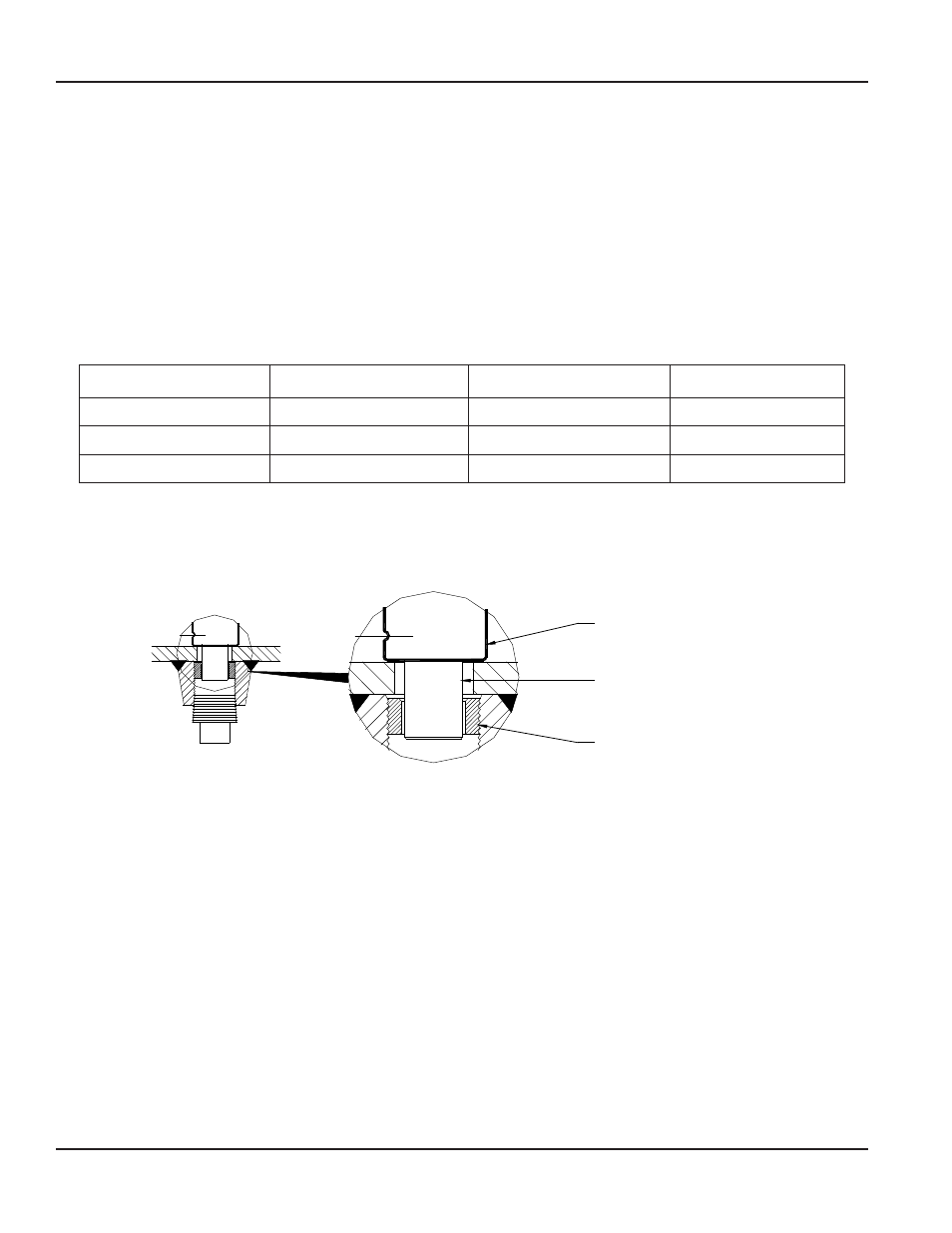
3 . Install the BHL Ellipse sensor through the two holes . Make sure that the double support pin passes through the guide ring .
See
Ellipse Sensor
Double Support Pin
Guide Ring
Figure 5: Double Support Pin
4 . Align the arrow on the sensor head in the direction of flow as in step 7,
“Installation Instruction, Single Support” on
5 . Check that the BHL Ellipse is in the correct orientation and spans the inside of the pipe . Tighten the threaded insertion
rods until the sensor reaches the other end of the pipe .
6 . Install the plug into the end of the double support thread-o-let . Tighten the plug to prevent leakage .
Ellipse® Pitot Tube Meter, BHL Annular Hot Tap Dual Rod Meter
Page 6
April 2014