Installation instruction, single support – Badger Meter Model BHL User Manual
Page 5
INSTALLATION INSTRUCTION, SINGLE SUPPORT
1 . Choose the proper location to install the BHL Ellipse using AGA/ASME standards (or equivalent) . See
2 . Grind the surface of the pipe where the BHL Ellipse is to be inserted to provide a clean area for welding .
3 . Weld the supplied thread-o-let to the pipe using standard codes for your application (1/16" weld gap recommended) . Take
care to protect the threads during the welding process .
4 . Thread the close nipple into the weld connector . Install the supplied three-piece isolating ball valve .
5 . Mount the high pressure drilling machine onto the ball valve . Open the ball valve . Drill a hole through the pipe wall
according to
.
Pipe Size
Model / Sensor
Weld Connector
Drill Bit
2"…5"
BHL (1/2")
3/4"
5/8"
6"…12"
BHL (7/8")
1-1/4"
1-1/8"
14"…24"
BHL (1-1/4")
1-1/2"
1-3/8"
Table 2: Single support drill bit size
OTEE:
N
There is no need for a drilling machine if it is not a hot tap installation or if the system is not pressurized .
6 . Withdraw the drill bit through the isolating ball valve . CLOSE the ball valve and dismantle the drilling machine . Make sure
there is no leakage at the valve and close nipple connections . The ball valve is to remain completely closed until step 9 .
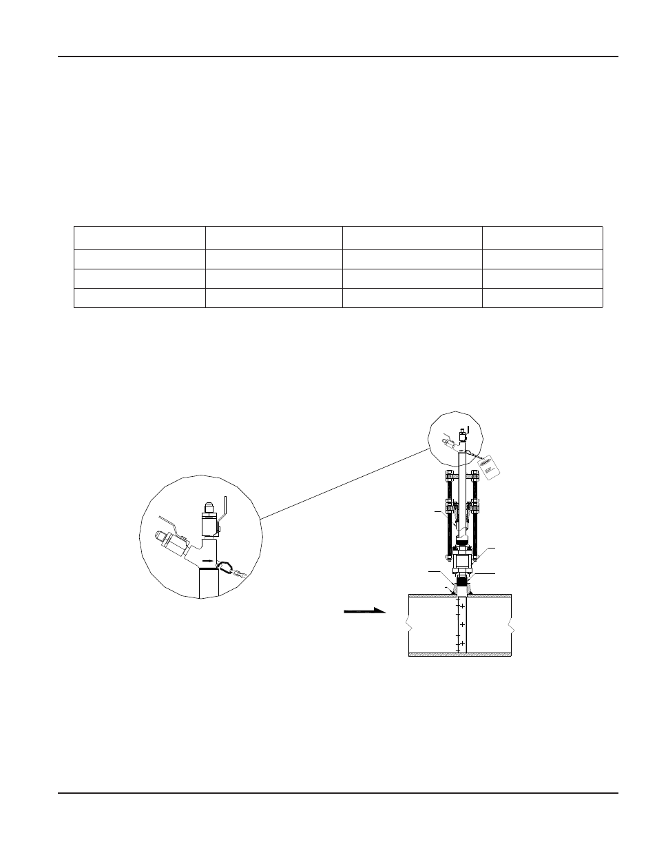
7 . Install the cage nipple assembly and packing gland with the threaded rods assembly by threading it into the isolating ball
valve . Align the arrow on the sensor head with the direction of flow . See
.
H
L
Field Weld
FLOW
Cage Nipple
Assembly
Weld
Connector
Isolating
Ball Valve
Close Nipple
H
L
Figure 4: Sensor alignment
User Manual
Page 5
April 2014