Installation instructions, single support – Badger Meter AHL-GD - Hot Tap, High Pressure (2 to 72")" User Manual
Page 5
User Manual
Page 5
April 2014
INSTALLATION INSTRUCTIONS, SINGLE SUPPORT
1 . Choose the proper location to install the AHL-GD Differential Pressure Flow Meter using AGA/ASME standards (or
equivalent) . Refer to the location diagrams
,
.
2 . Grind the surface of the pipe where the AHL-GD Differential Pressure Flow Meter is to be inserted to provide a clean area
for welding .
3 . Weld the supplied thread-o-let to the pipe using standard codes for your application (1/16 in . weld gap recommended) .
Take care to protect the threads during the welding process .
4 . Install the close nipple by threading it into the weld connector . Next, install the supplied 3-piece isolating ball valve .
5 . Mount the high pressure drilling machine onto the ball valve . Open the ball valve . Drill a hole through the pipe wall
according to
.
Model/Sensor
Weld Connector
Drill Bit
AHL-GD (7⁄8 in .)
1-1/4 in .
1-1�8 in .
AHL-GD (1-1/4 in .)
1-1/2 in .
1-3�8 in .
Table 2: Single support drill bit size
OTEE:
N
There is no need for a drilling machine if it is not a hot tap installation or if the system is not pressurized .
6 . Having drilled through the pipe, withdraw the drill bit through the isolating ball valve . Once the drill bit has been
withdrawn, close the ball valve and dismantle the drilling machine . Ensure that there is no leakage at the valve and close
nipple connections . The ball valve is to remain completely closed until step 9 .
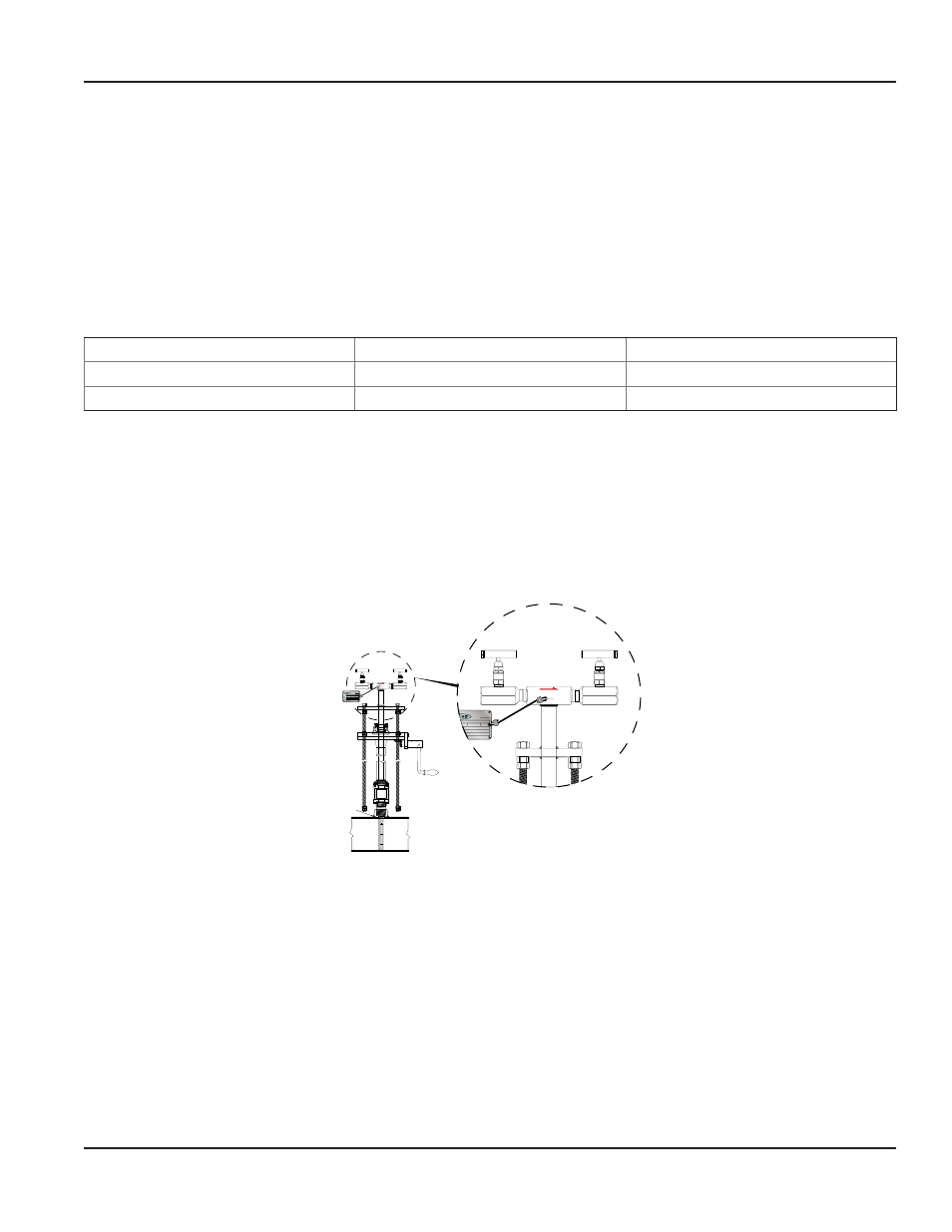
7 . Install the cage nipple assembly and packing gland with the threaded rods assembly by threading it into the isolating ball
valve . Align the arrow on the sensor head with the direction of flow . See
and
8 . Install the instrument valves (optional) at the pressure connections located on the AHL-GD Differential Pressure Flow Meter
sensor head . Ensure that the valves are fully closed before proceeding .
H
L
SCH/WALL
MOD/β
DIA/ID
CAP
DP
TAG
FLOW METERS
W/O
SCH/WALL
FLOW METERS
W/O
H
L
FLOW
FLOW
Field Weld
Figure 4: Flow indication arrow
9 . Open the isolating ball valve . Insert the AHL-GD Differential Pressure Flow Meter sensor into the pipe until it reaches the
opposite pipe wall . This should be done by turning the threaded insertion rods clockwise using a wrench .
10 . Connect the instrument lines to the sensor head valves . In turn, connect these lines to a gage or transmitter .