Series 200 or sdi – Badger Meter 340LW Series Lonworks Btu Transmitter User Manual
Page 5
5
Sensor Wiring
All flow sensor types connect to the four terminal
header labeled “sensor input”.
Series 200
Connect the red wire to sensor signal (+), black wire
to sensor signal (-) and the bare wire to shield.
SDI Series
Connect the plus (+) terminal of the sensor to
sensor signal (+) on the transmitter and the minus
(-) terminal of the sensor to sensor signal (-) on the
transmitter. Connect the shield terminal of the sensor
to the shield terminal of the transmitter.
Other Sensors
The sensor input Power Out terminal supplies
nominal 12VDC excitation voltage for 3 wire sensors.
Connect sensor signal + and sensor signal - wires to transmitter terminals.
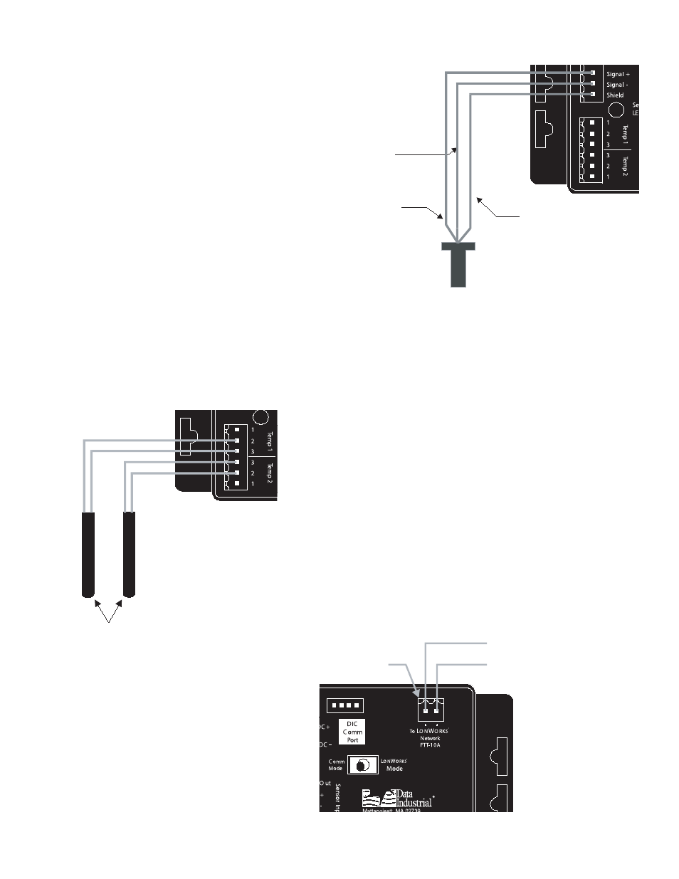
Temperature Element Wiring
The Badger Meter thermistors are not polarity sensitive.
Connect thermistor closest to the flow sensor to Series 340
terminal block marked TEMP 1 and the other thermistor wires to
Series 340 terminal marked TEMP 2.
Connecting the L
ON
W
ORKS
®
Bus
The L
ON
W
ORKS
network connection is not polarity sensitive.
Refer to”commissioning” section
10K
Ω Thermistors
S
uppl
y
Re
tu
rn
Thermistor Wiring Diagram
To ON
ORKS
Network
L
W
®
Not Polarity
Sensitive
Red
Black
Shield
(if applicable)
Series 200
or
SDI
Sample Sensor Wiring Diagram