Communications cable wiring, Cdrom installation, Web installation – Badger Meter Series 320 Pulse Transmitter User Manual
Page 3
3
Communications cable wiring
Field calibration requires a Data Industrial A320 Pro-
gramming kit (consisting of a custom cable and soft-
ware) and a PC running Windows® 9x, ME, NT, 2000 or
XP. In order to program, the
Model 320 must be connect-
ed to power, and the A301
cable must be connected to
the Model 320 Comm port
connector and an available
DB9 COM port on a com-
puter.
Note:
The Data Industrial A301 Cable will work with all 300
Series products. However the older version of the cable
(A300) does not have sufficient bandwidth to work with
the newer 340 Series Transmitters or SDI Flow Sen-
sors.
Programming Software Installation
Floppy Installation
Place the software installation Disk 1 into the floppy
drive and run the setup.exe program to install.
CDROM Installation
Software CD into the CDROM drive and it should auto-
start then Click software and click the product name for
what software you want installed and the installation will
begin.
Web Installation
Data Industrial provides free programming software up-
dates via the Internet for all of 300 Series devices. The
Installation software can be found at the Data Industrial
web site (www.dataindustrial.com) in the support sec-
tion.
Model 320 Programming
Programming the Model 320 is accomplished by install-
ing the Data Industrial programming software on a com-
puter and entering data on templates of the Windows®
based program.
1. Load the interface software into the computer.
2. Connect the computer to the Model 320 transmit-
ter using the Data Industrial A301 communications
cable. Plug A301 cable to the socket labeled “D.I.C
Comm Port” taking care to properly align the tab on the
plug and socket to maintain polarity then plug the DB9
connector of the Data Industrial A301 communications
cable to an avaliable PC com port that has the Model
320 software installed.
3. Connect the Model 320 transmitter to a power sup-
ply.
Data Industrial
Model 320 Installation Guide
3
Communications cable wiring
Field calibration requires a Data Industrial A320 Programming kit
(consisting of a custom cable and software) and a PC running Windows
®
9x, ME, NT, 2000 or XP. In order to program, the Model 320 must be
connected to power, and the A301 cable must be connected to the Model
320 Comm port connector and an available DB9 COM port on a
computer.
Note:
The Data Industrial A301 Cable will work with all 300 Series
products. However the older version of the cable (A300) does not have sufficient bandwidth to
work with the newer 340 Series Transmitters or SDI Flow Sensors.
Programming Software Installation
Floppy Installation
Place the software installation Disk 1 into the floppy drive and run the setup.exe program to install.
CDROM Installation
Software CD into the CDROM drive and it should autostart then Click software and click the product
name for what software you want installed and the installation will begin.
Web Installation
Data Industrial provides free programming software updates via the Internet for all of 300 Series
devices. The Installation software can be found at the Data Industrial web site (www.dataindustrial.com)
in the support section.
Model 320 Programming
Programming the Model 320 is accomplished by installing the Data Industrial programming software on
a computer and entering data on templates of the Windows
®
based program.
1. Load the interface software into the computer.
2. Connect the computer to the Model 320 transmitter using the Data Industrial A301 communications
cable. Plug A301 cable to the socket labeled “D.I.C Comm Port” taking care to properly align the tab
on the plug and socket to maintain polarity then plug the DB9 connector of the Data Industrial A301
communications cable to an avaliable PC com port that has the Model 320 software installed.
3. Connect the Model 320 transmitter to a power supply.
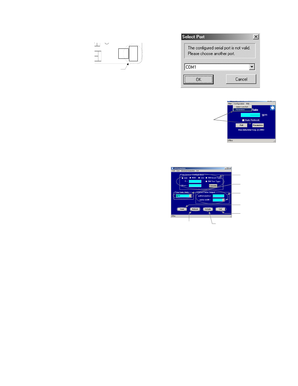
4. Open the interface software and select the appropriate COM PORT as shown in the dialog box
below.
Location of the
DIC Communication Port
S
P
ow
er
In
C +
C -
D.I.C.
Comm
Port
Input led
DIC
Communications
Port
Location of the
DIC Communication Port
Data Industrial
Model 320 Installation Guide
3
Communications cable wiring
Field calibration requires a Data Industrial A320 Programming kit
(consisting of a custom cable and software) and a PC running Windows
®
9x, ME, NT, 2000 or XP. In order to program, the Model 320 must be
connected to power, and the A301 cable must be connected to the Model
320 Comm port connector and an available DB9 COM port on a
computer.
Note:
The Data Industrial A301 Cable will work with all 300 Series
products. However the older version of the cable (A300) does not have sufficient bandwidth to
work with the newer 340 Series Transmitters or SDI Flow Sensors.
Programming Software Installation
Floppy Installation
Place the software installation Disk 1 into the floppy drive and run the setup.exe program to install.
CDROM Installation
Software CD into the CDROM drive and it should autostart then Click software and click the product
name for what software you want installed and the installation will begin.
Web Installation
Data Industrial provides free programming software updates via the Internet for all of 300 Series
devices. The Installation software can be found at the Data Industrial web site (www.dataindustrial.com)
in the support section.
Model 320 Programming
Programming the Model 320 is accomplished by installing the Data Industrial programming software on
a computer and entering data on templates of the Windows
®
based program.
1. Load the interface software into the computer.
2. Connect the computer to the Model 320 transmitter using the Data Industrial A301 communications
cable. Plug A301 cable to the socket labeled “D.I.C Comm Port” taking care to properly align the tab
on the plug and socket to maintain polarity then plug the DB9 connector of the Data Industrial A301
communications cable to an avaliable PC com port that has the Model 320 software installed.
3. Connect the Model 320 transmitter to a power supply.
4. Open the interface software and select the appropriate COM PORT as shown in the dialog box
below.
Location of the
DIC Communication Port
S
P
ow
er
In
C +
C -
D.I.C.
Comm
Port
Input led
DIC
Communications
Port
4. Open the interface software and select the appro-
priate COM PORT as shown in the dialog box below.
5. Open the Parameters Screen as shown below.
6. Program using diagram below as a reference
Note #1
Sdi - If the SDI sensor type is selected the required
K and offset values can be found the the SDI owners
manual.
4000 - If the 4000 sensor type is selected, click the
choose button and select the sensor from the pull down
box that appears.
Sine - Provided for connection to sensors which have a
sine wave output. Please consult sensor manufacturer
for the calibration settings.
200 Insert Type - If the 200 Insert Sensor type is
selected the required K and offset can be found the
the 200 owners manual or if the manual is not handy
the calculate button can be pushed and an inside pipe
diameter can be entered and once calculate is pressed
a K and offset will automatically be entered in.
200 Tee Type - If the 200 tee type is selected, click the
choose button and select the sensor from the pull down
box that appears.
Data Industrial
Model 320 Installation Guide
4
6. Program using diagram below as a reference.
Note #1
Sdi - If the SDI sensor type is selected the required K and offset values can be found the the SDI
owners manual.
4000 - If the 4000 sensor type is selected, click the choose button and select the sensor from the pull
down box that appears.
Sine - Provided for connection to sensors which have a sine wave output. Please consult sensor
manufacturer for the calibration settings.
200 Insert Type - If the 200 Insert Sensor type is selected the required K and offset can be found the
the 200 owners manual or if the manual is not handy the calculate button can be pushed and an inside
pipe diameter can be entered and once calculate is pressed a K and offset will automatically be entered
in.
200 Tee Type - If the 200 tee type is selected, click the choose button and select the sensor from the
pull down box that appears.
To go to calibration settings
screen select "Parameters"
from either place shown
5. Open the Parameters Screen as shown below.
Step #2
Select Flow Rate Units.
Step #1
See Note #1
Select Sensor Type and
Enter K and offset numbers.
Step #3
Enter units per pulse and select
pulse width.
Step #4
Send
Press
to transmit
calibration data to the 320.
Press to refresh the parameters
screen with the current 320 settings.
Press to restore the factory defaults
To save the factory defaults Send
must be pressed before values take effect.
Step #5
Press to exit Parameters screen and
go back to the main screen.