Console functions, Channel strip – Audient ASP4816 - Compact Analogue Recording Console User Manual
Page 23
Page -23-
© Audient Ltd
Console functions.
There are 3 back illuminated
indicators showing the selected
input to the SF path. This can be
changed between Mic/Line and
DAW using the FLIP switch.
LF Source allows the source for
the SF path to be taken from
the LF path. This could be used
during mixdown to send the LF
signal through the SF path up to
the routing matrix where the bus
outputs can be used as additional
effect sends. Normally this signal
is derived after the long fader
(POST LF) but it can be made PRE
LF by changing an internal link on
the circuit board.
The source switching occurs before
the equaliser so it is possible
to equalise the SF signal which
has been taken from the LF path
by switching either one or both
equaliser sections into the SF path.
(If this is done then the equaliser
section is no longer available in
the LF path).
The SF PAN control allows
panning across the bus outputs
when pan is selected on the routing
section of the strip.
MIX allows the SF signal to be
routed to the stereo mix bus and
allows the SF path to be used as an
additional input during mixdown.
The short fader is designed for use
with 10dB of gain in hand allowing
the signal to be boosted or reduced
in level if required.
The SOLO switch allows the
channel to be auditioned through
the AFL/PFL or Solo in Place
facilities.
CUT allows the SF signal path to
be muted.
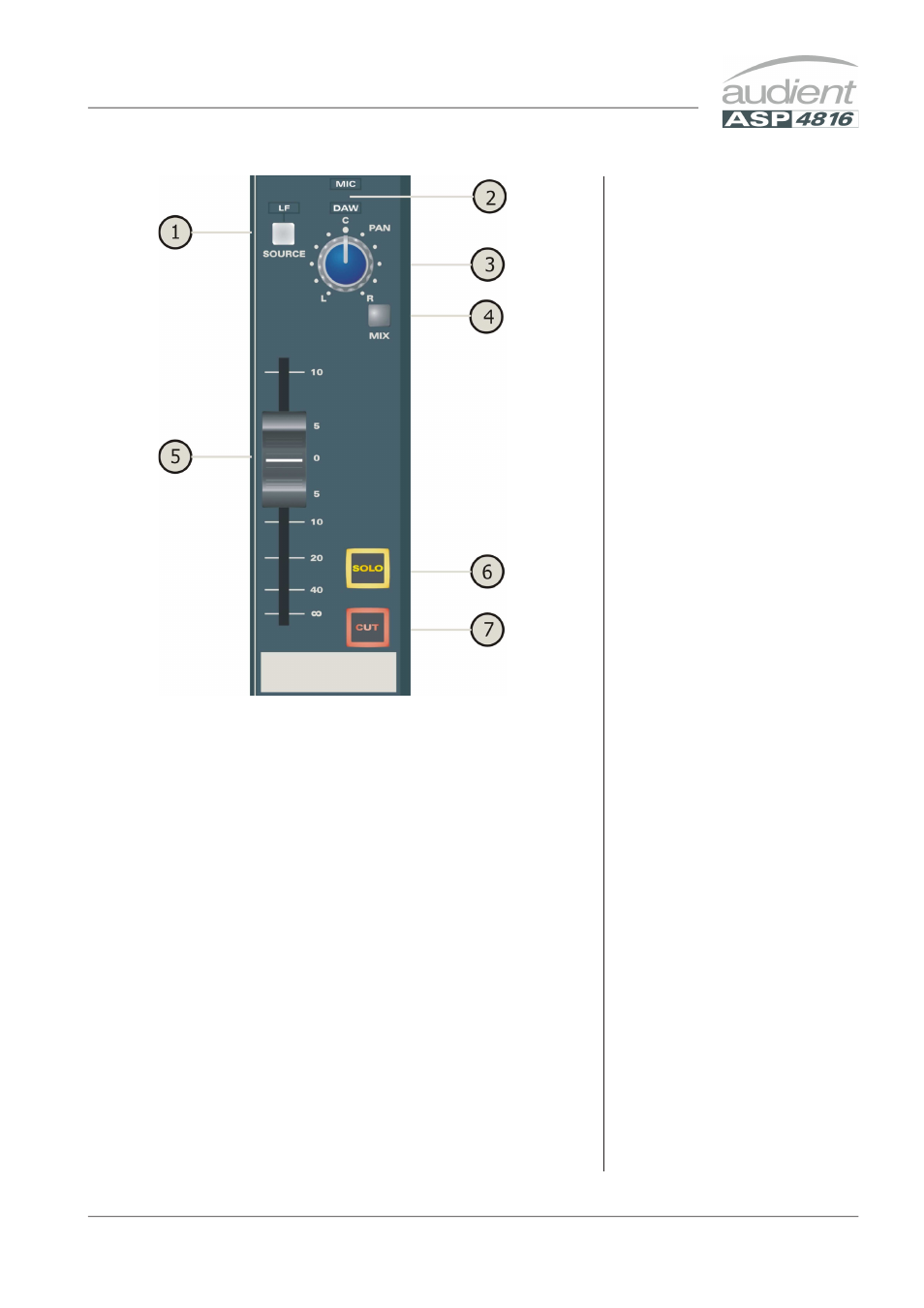
SHORT FADER (SF)
1 SOURCE selects the post fade
LF signal as the input to the
SF signal path, over-riding the
MIC or DAW selection from
the Flip switch. By altering a
link on the circuit board this
signal can be made pre fade.
The LF legend will illuminate
when the switch is pressed and
the MIC/DAW indicator will
blank.
2 MIC/DAW. These back lit
indicators show whether the
MIC/LINE or the DAW input
is selected to the SF path. Only
one will be illuminated and it
can be changed by using the
FLIP switch.
3 This is the PAN control for
the SF signal enabling it to be
panned across odd and even
buses.
4 MIX routes the SF signal
to the stereo mix bus. It is
good practice to unroute
any channels which are not
needed. This will reduce mix
amp noise.
5 This is the SHORT FADER
which controls the level of the
SF signal.
6 SOLO allows the SF signal to
be heard on the monitors and
viewed on the master meters.
If Solo In Place is selected
it will replace the console
output.
7 CUT allows the SF signal
path to be muted. This may
help to reduce noise in a mix
if a channel is not in use for a
period of time.
CHANNEL STRIP