Seametrics iMAG-Series User Manual
Page 8
Page 6
Meter Equalization Lug
Plastic Pipe
Plastic Pipe
#6 AWG Stranded
Copper Ground Wire
Ground Clamp
8’ Ground Rod
Earth
Exothermically weld when
corrosion is a concern
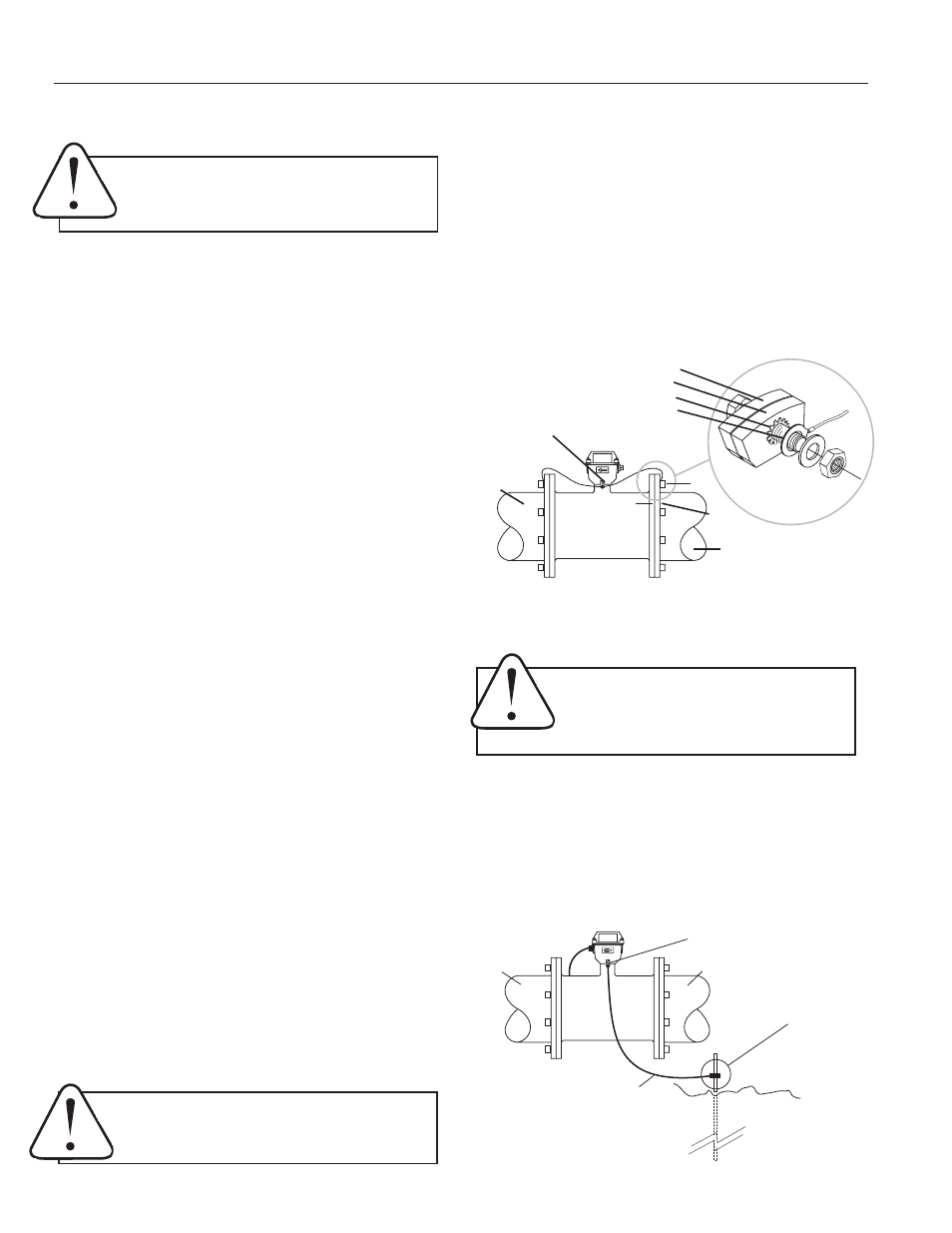
EQUALIZATION AND GROUNDING
Metal Pipe Installations.
To equalize the electrical potential
of the fluid, the iMAG meter, and the surrounding pipe, secure
the flange plates (factory-installed on the equalization wire)
to both pipe flanges at one of the bolt holes, as shown below.
Be sure the lockwasher fits between the pipe flange and the
flange plate. For the best electrical bonding, remove rust
and paint to expose clean, bare metal where the equlization
flange plate lockwasher contacts the pipe flange. Connection
must be inspected periodically for corrosion to maintain the
necessary low resistance connection.
Equalization Diagram
Equalization Lug
Meter
Flange
Pipe
Flange
Bolt
Run wire from equalization lug to both pipe flanges;
secure flange plates under bolt heads as shown.
Meter Flange
Pipe Flange
Flange Plate
Lockwasher
WARNING: ELECTRICAL SHOCK HAZARD
When
the meter is externally AC powered the piping
system must be grounded to meet national and
local electrical safety codes. Failure to do so can
result in electrical shock and/or burn.
Plastic Pipe Installations.
When the iMAG is installed in a
plastic piping system, it is not necessary to use the equaliza-
tion straps, but very important to ground the meter to avoid
electrical shock hazard and electrostatic interference with
meter function. If the rate display is unstable, grounding
rings may be necessary.
INSTALLATION
Positioning the Meter.
These meters can be installed
horizontally, vertically, and in any radial position. Using a
check valve on the upstream side of the meter, and/or an air
vent (vacuum relief valve) in the same, unobstructed run of
pipe as the meter, is required in any installation where the
meter may be exposed to suction when the system is not in
normal operation. Suction can cause damage to the liner.
Liner damage caused by suction, without the use of a check
valve and/or air vent, may void the warranty.
Straight Pipe Recommendations.
As with most flow meters,
the iMAG requires straight pipe before and after the meter for
best accuracy. However, the ability of electromagnetic meters
to average the flow across the entire pipe allows for shorter
straight pipe recommendations than most mechanical meters
(see page 7).
Full Pipe Recommendations.
All magmeters require a
method for determining that the pipe is empty, to prevent false
reading. This meter is designed to indicate ‘EMPTY PIPE’ if one
or more electrodes is exposed. For highest accuracy, install
the meter so that the pipe will be full when there is flow. If air
bubbles may be present in the pipe or sludge accumulation
is an issue, rotate the meter by one flange hole to position
the control housing at a 45˚ angle (see diagrams on page 8).
Fittings.
The iMAG flanges have standard ANSI 150 lb. drilling
pattern and mate with any other ANSI 150 lb. flange.
Calibration.
The iMAG is factory-calibrated and will not require
any form of field calibration.
Caution:
These flow sensors are not recommended
where installation fault may expose the flow sensor to
boiler pressure and temperature. Maximum
recommended operating temperature is 130˚ F.
INSTALLATION and GROUNDING
Chemical Injection.
When any magmeter, by any manufac-
turer, is used in a chemical injection application, the chemical
injection point must be placed downstream of the magme-
ter OR far enough upstream for complete mixing to occur
before the fluid reaches the meter
. When unmixed chemical
alternates with water passing through the meter, the rapid
changes in conductivity may cause sudden spikes and drops
in the meter’s reading, resulting in inaccurate measurement.
The magmeter will restabilize, however, with a steady flow of
fluid of uniform conductivity.
Metal
Pipe
Metal
Pipe
Caution:
In chemical injection applications, install
chemical injection point downstream of magmeter,
or far enough upstream to allow complete mixing
of fluids.
Partially Open
Butterfly Valve