Warning – Seametrics iMAG-Series User Manual
Page 12
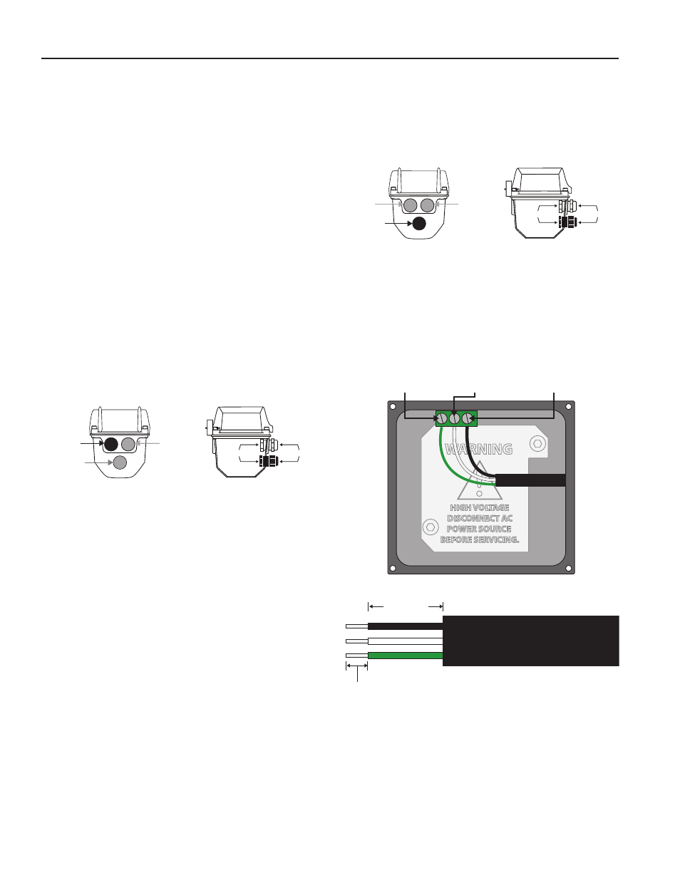
1. Using a 5/32” hex driver, remove the four cap screws
securing the top housing to the lower housing and swing
the top open to expose the internal wiring and components.
2. Loosen the cable gland sealing nut, remove the plug
and insert the unconnected cable end through the open
hole.
3. Strip cable jacket and conductors (see below) and install
3-conductor power cable and wire to Line (L), Neutral (N)
and Ground (G) positions on power supply terminal block
as shown below
4. Tighten terminal block screws securely using 1/8”
(3mm) screwdriver. Tighten the cable gland sealing nut
securely. A loose nut could cause moisture ingress and
compromise the meter head’s IP67 rating, voiding the war-
ranty.
5. Close the top cover and replace the four cap screws,
securing tightly to reseal the housing against moisture
ingress.
Page 10
INPUTS/OUTPUTS and OPERATION
WIRING TO POWER SOURCES AND EXTERNAL MONITORING
AND CONTROL EQUIPMENT
The six-conductor Control Cable exiting the display head
provides user connections for DC power as well as for external
monitoring and control equipment needed for pump control,
SCADA equiment, Programmable Logic Controllers, remote
displays and other monitoring equipment. A four-character
Option Identifier (OID) code found in the “Control Cable Wiring”
table on page 11 shows available combinations of external
wiring connections. In addition, it gives the corresponding
electrical function for each of the wires in the cable. The OID
code is also included in the model number on the meter as well
as on the label attached to the control cable as shipped from
the factory. The first character in the OID code identifies the
power source as either external DC (D) or internal AC (A). The
next two characters identify the functions of the other wiring
options such as Pulse Output (P), Telemetry (T), Analog Output
(L), Digital Output (D), Relay Output (R) or Serial Output (SS.)
(The fourth character (X) is reserved for future applications.)
Application, wiring and other electrical interface guidelines for
each of these is outlined in the following paragraphs.
DC Power Connection.
When the first OID code character is
a “D”, connect the RED and BLACK wires to the positive and
negative terminals respectively of a clean (low-noise) source
of dc power in the range of 9-32Vdc and able to supply at least
250mA. AC line-operated power supplies with outputs greater
than 18Vdc must be regulated. Where possible, connections
from either power supply terminal to the cable shield or any
other ground should be avoided.
AC Power Connection.
When the first OID code character
is “A”, the RED and BLACK wires are not used. Instead, 85-
264Vac power is supplied to the flow meter via a separate
meter housing cable-entry gland and user-supplied three-
conductor power cord having local regulatory agency approval.
If installed outdoors or less than 33 ft. (10m) from a utility
power service entrance, ac power should be supplied via a
properly-grounded surge suppression device. See diagrams
below for wiring instructions.
Sealing Nut
Bulkhead Nut
Control Cable
Sensor Cable
AC Power Cable
Sealing Nut
Bulkhead Nut
Control Cable
Sensor Cable
AC Power Cable
2” (50mm)
3/8”
(10mm)
WARNING
!
HIGH VOLTAGE
DISCONNECT AC
POWER SOURCE
BEFORE SERVICING.
Green
(North America)
Green-Yellow
(International)
GROUND
White
(North America)
Blue
(International)
NEUTRAL
Black
(North America)
Brown
(International)
LINE