Page 11 inputs/outputs and operation – Seametrics iMAG-Series User Manual
Page 13
Page 11
INPUTS/OUTPUTS and OPERATION
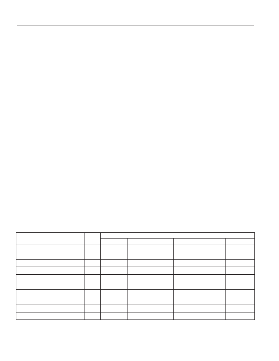
Power
Source
Options
Installed
OID
Codes
Cable Conductor Usage
Red
Black
Green
White
Orange
Blue
DC
None
DPTX
DC PWR +
DC PWR -
Pulse +
Pulse -
3.3V Comm TXD
3.3V Comm RXD
DC
One Pulse, 4-20mA Output
DPLX
DC PWR +
DC PWR -
Pulse +
Pulse -
4-20mA Out +
4-20mA Out -
DC
One Digital Output
DDDX
DC PWR +
DC PWR -
Out 1 +
Out 1 -
Out 2 +
Out 2 -
DC
4-20mA Output 1 Digital Output
DDLX
DC PWR +
DC PWR -
Out 1 +
Out 1 -
4-20mA Out +
4-20mA Out -
DC
One Pulse Output
DPXX
DC PWR +
DC PWR -
Pulse +
Pulse -
Do Not Connect
Do Not Connect
AC
None
APTX
Do Not Connect
Signal Ground
Pulse +
Pulse -
3.3V Comm TXD
3.3V Comm RXD
AC
One Pulse, 4-20mA Output
APLX
Do Not Connect
Do Not Connect
Pulse +
Pulse -
4-20mA Out +
4-20mA Out -
AC
One Digital Output
ADDX
Do Not Connect
Do Not Connect
Out 1 +
Out 1 -
Out 2 +
Out 2 -
AC
4-20mA Output 1 Digital Output
ADLX
Do Not Connect
Do Not Connect
Out 1 +
Out 1 -
4-20mA Out +
4-20mA Out -
AC
One Pulse Output
APXX
Do Not Connect
Do Not Connect
Pulse +
Pulse -
Do Not Connect
Do Not Connect
Control Cable Wiring
Pulse Output Connection.
When the second OID code
character is “P”, refer to the “Digital Output Application”
diagrams on page 12 for recommended pulse output
connections to external equipment. Since this is an isolated
output, the external equipment must include a dc power
source to regenerate the pulse from the open-collector
output (transistor equivalent of a contact closure). A pull-up
or pull-down resistor may be needed if not included in the
user equipment as shown in the diagrams. Both the power
source and resistor may be supplied internally in some
types of control and monitoring devices. If not, as for most
PLC discrete input modules, they must be added externally
at the module input terminals. Pulse output rate in volume
units/pulse is user-settable via the SET P tab on the meter’s
setup menus.
Analog Output (4-20mA) Connection.
When the second or
third OID code character is “L”, refer to the “Analog Output
Application” diagram on page 12 for 4-20mA current loop
output connections to external analog input devices. Since
the meter’s analog output is isolated and passive loop
power must be supplied externally as shown. (In addition, an
external resistor R
L
will be needed to convert the loop current
to voltage for voltage-only input devices.) The meter’s loop
transmitter minimum voltage drop is 6V which, with wiring
resistance and loop power supply voltage, will determine the
maximum resistance for R
L
. The flow rates corresponding to
4 and 20mA are user-settable via the SET 4 and SET20 tabs
on the meter’s setup menus.
Digital Output Connection.
When the second or third OID
code character is “D”, refer to “Digital Output Application”
diagrams on page 12 for recommended connections to
external equipment. These outputs are essentially the same
as the Pulse Output described above except they are capable
of output frequencies up to 10kHz. Frequency output scaling
is user-settable via the FOUT tab on the meter’s setup menus.
Selections are: 500Hz and 1, 2, 5 and 10 KHz.
Cable Shield.
In general, the cable shield and its bare drain
wire should be left unconnected at the user equipement end
of the cable to minimize “ground loop” problems.