Seametrics iMAG-Series User Manual
Page 11
Page 9
INPUTS/OUTPUTS and OPERATION
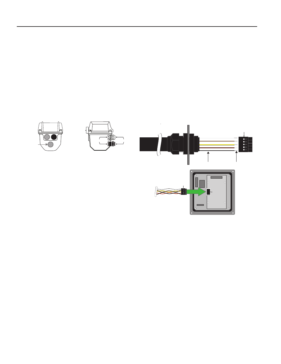
REMOTE SENSOR CABLE INSTALLATION (iMAG3600 ONLY)
The standard 33 foot (10m) cable connecting the iMAG3600
sensor body to the remote display head is shipped with the
cable disconnected at the display end. To connect during
installation:
1. Remove the four cap screws securing the top housing
to the lower housing and swing the top open to expose the
internal wiring (see photo.)
2. Remove the sensor cable hole plug and discard.
3. After removing the cable gland bulkhead nut, insert the
5-postion plug and cable gland threaded bushing into the
open hole. (see drawing.) Do not loosen the cable jacket
sealing nut.
4. Install the bulkhead nut back onto the cable gland threads
inside the housing and tighten securely. A loose nut could
cause moisture ingress and compromise the meter head’s
IP68 rating, voiding the warranty.
5. Insert the five-position plug into the mating receptacle on
the small circuit board attached to the larger main display
circuit board.
6. Close the top cover and replace the four cap screws, securing
tightly to reseal the housing against moisture ingress.
7. Do not remove gel packs.
Shortening the Sensor Cable.
The sensor cable may be
shortened by cutting the cable at the display head end. Under
no circumstances should the cable gland at the sensor body
end be removed as this will compromise the IP68 moisture
ingress protection causing meter failure and voiding the
warranty. To shorten the cable follow the steps below:
1. Before cutting, loosen the cable gland sealing nut and slide
the gland back past where the cable will be cut.
2. After cutting, remove the jacket and outer braid shield
and cut and strip conductors to the dimensions shown in the
drawing (right). Tinning the bare wire ends is recommended
when possible for easier reinsertion into the 5-position plug.
3. Insert a small jeweler’s screwdriver or pick into the slot
next to the black wire on the 5-position plug and pull the wire
out. Then insert the black wire from the shortened cable into
the same position as the wire just removed. Repeat this step,
one wire at a time, for all five positions.
4. Remove the sensor cable hole plug and discard.
5. After removing the cable gland bulkhead nut, insert the
plug and cable gland bushing through the open hole. Install
the nut back onto the cable gland threads inside the housing
and tighten securely. A loose nut could cause moisture ingress
and compromise the meter head’s IP68 rating, voiding the
warranty.
6. Slide the cable outward through the loosened cable gland
until the jacket just protrudes past the cable gland bulkhead
threads.
7. Retighten the gland sealing nut until cable cannot be
pushed in by hand and then tighten an additional full turn.
Pull on cable to assure sufficient tightness.
8. Insert the five-position plug into the mating receptacle on
the small circuit board attached to the larger main display
circuit board.
9. Close the top cover and replace the four cap screws,
securing tightly to reseal the housing against moisture ingress.
Lengthening the Sensor Cable.
Replacing the entire cable
with a longer cable is not recommended. To extend the
distance from the sensor body to the remote display head:
1. Install a junction box with two holes for 5/8” connector
bushings at the cable splicing location.
2. Install the sensor cable gland threaded bushing into one
junction box hole and secure with the bulkhead nut.
3. Obtain the required additional length of 2-pair Seametrics
sensor cable and two additional cable glands, installing the
additional cable and glands from the junction box to the display
head. Secure all cable gland sealing and bulkhead nuts to
tightness required to prevent moisture ingress as described
in previous instructions. Use pull test to assure sufficient
tightness.
4. Splice wires in junction box using moisture-sealed wire
connectors or pot to seal against moisture ingress. Replace
junction box sealing cover.
5. Connect 5-position plug to the small circuit board receptacle
in the display head as described in previous instructions.
6. Warning! Extending the length of the sensor cable
beyond 100 feet (30 meters) may cause the meter to
malfunction.
5-Position Plug
Position 1 - Drain
Position 2 - Brown
Cable from
Sensor
Position 3 - Yellow
Position 4 - Orange
Position 5 - Black
1
2
3
4
5
.20” (15mm) Splice
4” (102mm) Wire Length
Lower Housing Bulkhead
Mating Receptacle
5-Position Plug
1
2
3
4
5
Top Housing
Control Cable
AC Power Cable
Sensor Cable
Sealing Nut
Bulkhead Nut