1 thermocouple input wiring, 2 relay wiring, 3 auxillary power supply wiring – Pyromation Series 423 User Manual
Page 8
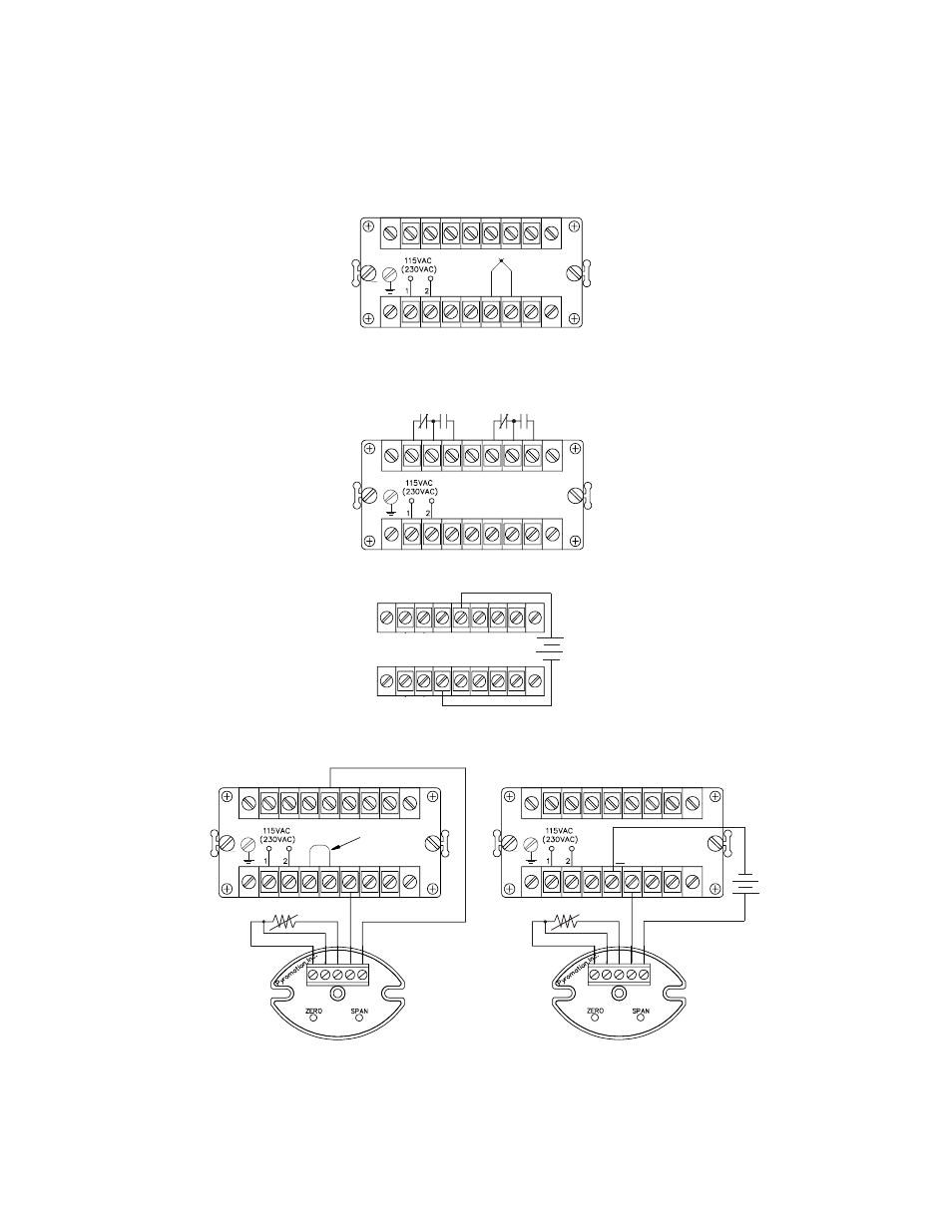
7-1
THERMOCOUPLE INPUT WIRING
Page 7
GND
4
-
+
RTD
WHITE
RED
RED
5
+
GND
4
3
-
-
11
+
+
RTD
WHITE
RED
RED
5
JUMPER
GND
T/C
+
-
T/C
5
6
Figure 12
Note: Thermocouple input extension wire should not be run in the same conduit as line voltage, nor should they be
exposed to excessive electrical noise. Always use compensated leadwire when wiring for thermocouple inputs.
7-2
RELAY WIRING
8
9
10
12
13
14
ALARM 2
ALARM 1
GND
11
Figure 13
Figure 15 -
with Loop Power
7-3
AUXILLARY POWER SUPPLY WIRING
Figure 14
3
11
-
+
24 VDC
OUTPUT
7-4
4 - 20mA INPUT with and without INTERNAL LOOP POWER
Figure 16 -
without Loop Power
*
See note on Page 11