Sil-3 elektronic – NOSHOK 5301 Series Load Pins User Manual
Page 6
Operating manual
5301 Series Load Pins
6
Please note the following:
• Always use shielded, low-capacity measuring cables
(all tecsis cables meet these requirements, see chapter 10.1).
• Do not route the measuring cable parallel to high-voltage current and
control cables.
• Avoid leakage fields from transformers, motors and contactors.
• The transducer, the amplifier and the display unit must not have
multiple grounds. Attach all equipment to the same protective
conductor.
SIL-3 Elektronic
Amplifier-Electronics 4...20mA or 0...10V
for SIL-3 applications with 2-channel PC control
NOSHOK, Inc.
•
1010 West Bagley Road, Berea, OH 44017
•
Ph: 440.243.0888
•
Fax 440.243.3472
•
www.noshok.com
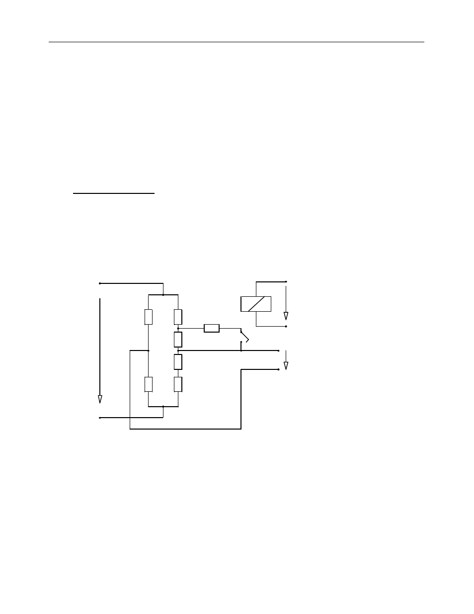
This well proven design has been amended by an additional resistor R7
in order to monitor the condition of the amplifier unit and signal path.
This resistor is connected as a shunt to resistor R5 by a relay contact
(a) as soon as an excitation voltage U
r
appears at relay A.
a
R5
R6
R4
R3
R2
R1
A
Ur
R7
Ub
U0
The connection of resistor R7 will always result in a defined unbalancing
of the zero point (diagonal voltage) of the Wheatstone Bridge.
An external independent control unit activates relay A which changes
the output by a certain value. Because of security reasons the control
unit has to be a 2-channel one. When the expected change of the
output signal is detected it can be assumed that the whole signal path
(Wheatstone Bridge – amplifier – output) works well.
If it does not appear it can be concluded that there is a defect in the
signal path.
The standard adjustment of force transducers with current output for
overload control is e.g.: