4 simulating a transmitter, Loop power supply 30 vdc max uut – Martel Electronics PSC4010 User Manual
Page 15
13
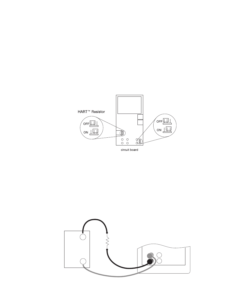
4.3-1 HART™ Resistor Selection
The PSC4010 can be set-up so that the 250 ohm resistor required for Hart™ configuration
devices resides inside the PSC4010. Enabling the PSC4010's internal 250 ohm resistor
eliminates the need to manually add a series resistor during a Hart™ calibration process.
NOTE: When the PSC4010's internal 250 resistor is enabled, maximum load driving
capability drops from 1000 ohms @ 20mA to 750 ohms @20mA.
Enable/Disable Procedure
1. Remove the battery cover and remove the 2 screws that are at the top of the case.
2. Remove the 2 screws on the bottom or lower portion of the case.
3. Gently remove the top half of the case from the bottom.
4. Figure 9. shows the location of the Hart™ jumpers.
Figure 9.
4.4 Simulating a Transmitter
To have the calibrator supply a variable test current to a loop in place of a transmitter, follow
these steps:
1.
Select the [CONFIG] option from the main menu.
2.
Choose mA simulation from the primary parameters [mA 2W SIM], and enter the desired
current.
3.
Connect the 24V loop as shown in Figure 10.
Figure 10. Connections for Simulating a Transmitter
MEASURE / SOURCE
3W
mA+
+
V
Hz
–
Ω
4W
mA–
–
–
+
+
LOOP
POWER
SUPPLY
30 VDC
MAX
UUT