KYORITSU 6017 User Manual
Page 21
19
6-5 Earth Resistance Measurement
The earth resistance function is used to check that equipment is properly earthed
to provide appropriate protection against shock hazard to the user or damage to
the equipment.
Select the precision or simplified mode, then select the desired measuring range.
Use the optional test leads for precision measurement.
DANGER
¡
Never touch the tips of the test leads or the circuit under test during earth
resistance measurement to avoid possible shock hazard. When the test
button is pressed, a voltage of up to 50V AC is present across the terminal
E and C, or E and P.
6-6 Precision Measurement ( 3 POLE )
For precision measurement, use the optional test leads and auxiliary earth spikes.
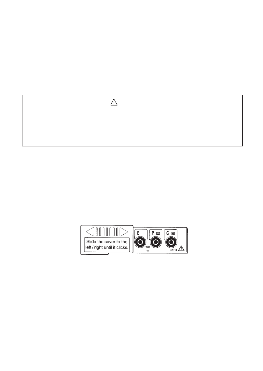
1. Slide the sliding shutter over the probe socket to reveal the terminals for
precision earth resistance measurement. Insert the plug of each test leads into
the appropriate terminal (E: Green lead, P: Yellow lead, C: Red lead).
2. Drive auxiliary earth spike P and C deep into the earth as shown in the figure
below. They should be aligned at an interval of 5 to 10 meters from the earth
electrode under test. Using the alligator clips of the test leads, connect the earth
electrode to terminal E, earth spike P to terminal P, and earth spike C to
terminal C.
If it is not possible to align the earth electrode and the auxiliary earth spikes,
position the earth spikes so that they and the earth electrode form an angle of
100 degrees or greater. This will allow accurate earth resistance measurement.