Electrical connection and settings, Dwm1000 flow switch – KROHNE DWM 1000-2000 EN User Manual
Page 5
5
Electrical Connection and Settings
Electrical Connection
n The wiring terminals for the DWM can be found in the connection chamber (see page 3, item 11).
n The electrical connection conforms to the standard EN61010-1, protection class 1, voltage category II, interference degree 2. n
n The DWM range conforms to EMC directives NF EN 50 081.1 (Emission) and NF EN 50 082.2 (Immunity)
n For DWM
1000 see “ERRATA DWM 1000 Flow Switch”
DWM1000 Flow Switch
n Terminals 1 and 2 are used for the electrical connection (wire
cross-section: max. 1.5mm2 or 16 AWG). Polarity is arbitra-
ry.
n The flow switch must not be connected to power without an
electrical load in series (e.g. relay)!
n The choice for the alarm status NO (circuit open for velocit
Setting of the Alarm Status
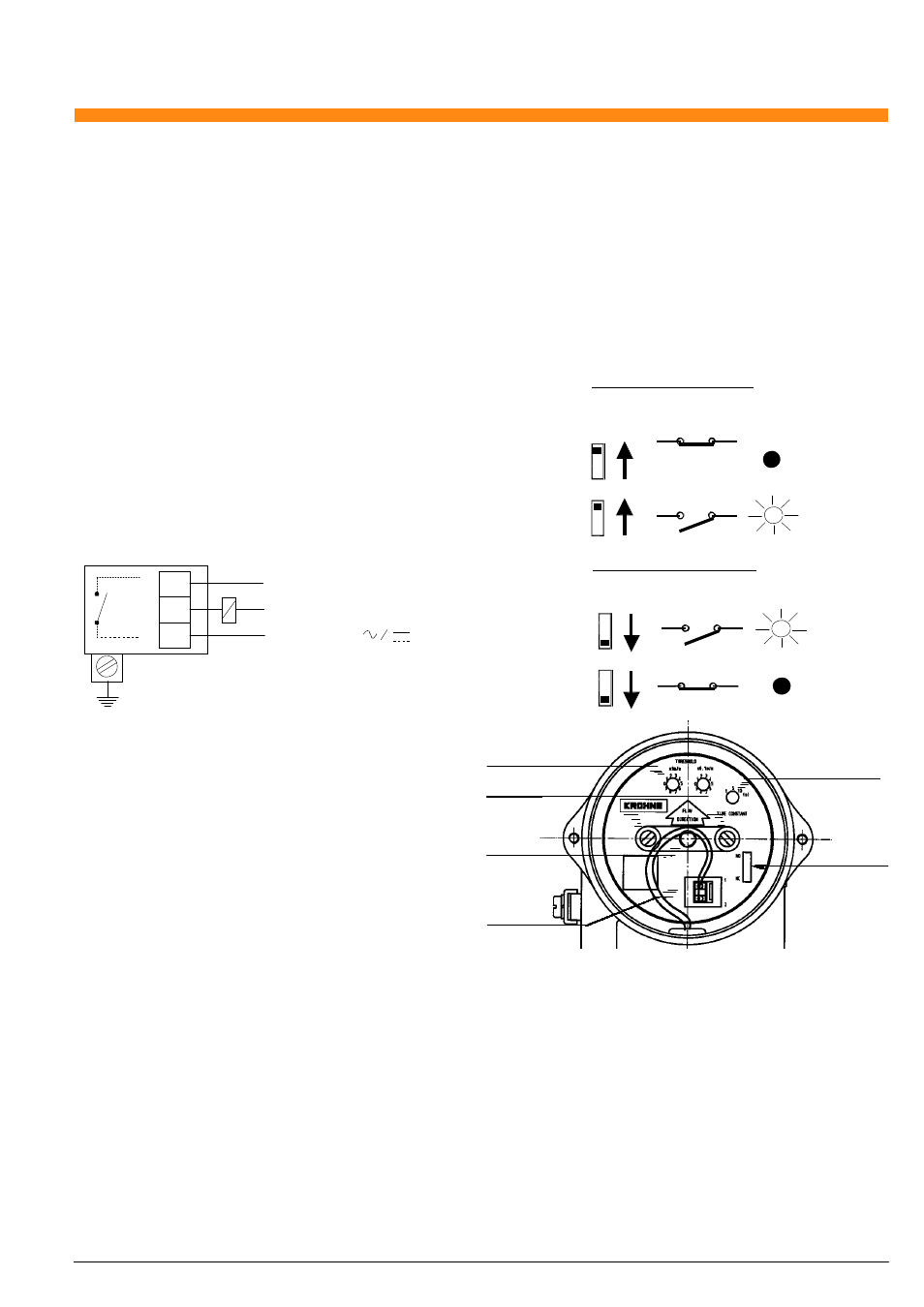
The alarm status can be selected with the invertor (13).
NO - circuit open for velocity higher than reference velocity.
NC - circuit closed for velocity higher than reference velocity.
The LED flashes when the circuit is open.
Make Contact Status (NO)
Internal
higher than reference velocity) or NC (circuit open for inverse
function) can be changed by the switching as detailed on the
right.
n If more than one DWM1000 is used, make sure they are not
connected in parallel. Only one common return is allowed.
Provide a separate fuse for each flow switch.
n Ensure that the earthing of the unit is <10 Ohms.
V V>Vref NO/NC Selector NO Switch LED Off Flashing PE Protective Earth Break Contact Status (NC) Internal LED DWM 1000 1 2 Load e.g. Relay U: 48 - 240 V V NO/NC Selector NC Switch Flashing FE < 10 Ohms (Functional Earth for housing) Relay Limits with compatibility specifications. Refer to the ‘Compatible Relay ’ section for the choice of relay on page 7. Settings V>Vref NC Reference Velocity ref (11) Mounting Screws (14) LED Off Time Constant Dial (12) n Positioning of the electronic block. Open the housing and unscrew the two mounting screws (14) of Setting of the Reference Velocity Setting of the Time Constant (10) Selector NO/NC (13) Power Installation on Piping With Cathodic Protection Removal and Remounting of the Electronic Block
NO
n Always ensure that the voltage and relay voltage correspond
The settings have to be carried out in the following order:
Dials for V
n Setting of reference velocity.
n Setting of the time constant.
n Setting of the alarm status: NO or NC.
the electronic block (only two turns) without taking them out.
Position the block aligning the arrow with the direction of flow in
the pipe (if not aligned false readings will occur). The block is
then fixed by fully tightening the mounting screws.
Set the reference velocity with the two dials (11), one for the
m/s units and the other for the 1/10ths units.
Set the time constant with the dial (12) to 5, 8 or 10 seconds.
Depending on the desired function of the unit, program the time
constant to the largest possible, to avoid unnecessary swit-
ching during fluctuations in the flow rate.
Terminals (9)
Please contact KROHNE directly for instructions.
The electronic block may be removed in security during flow
conditions, as the probe is fully sealed. Before removing the
unit ensure that the power supply is switched off. Unscrew the
two mounting screws fully (14), and pull the block by means of
the plastic bridge.
To replace the block, it should be orientated so that the screws
(14) engage into the threads of the rotating sleeve, and secured
in place with a few turns. Next orientate the block so that the
arrow is in line with the flow direction, and lock the block by fully
tightening the mounting screws.
Note - the replacement block needs to be calibrated.