Technical data – KROHNE OPTIFLUX 7300 EN User Manual
Page 27
TECHNICAL DATA
6
27
OPTIFLUX 7300
www.krohne.com
01/2011 - 4001163301 - MA OPTIFLUX 7300 R01 en
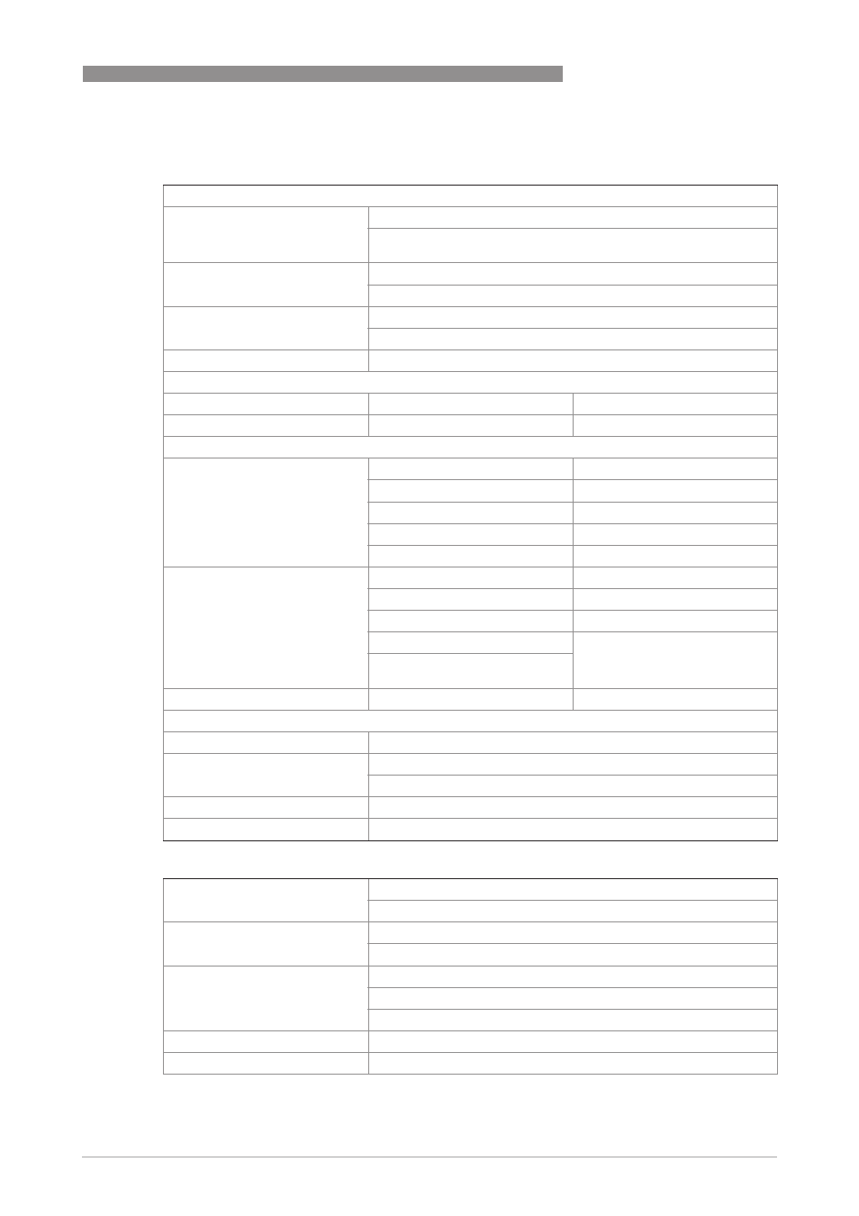
Operating conditions
Temperature
Temperature
Temperature
Temperature
Process temperature
-40...100°C / -40...+212°F (up to 120°C / 248°F for up to 30 min.)
For Ex versions different temperature ranges are applicable.
Please see the relevant Ex documentation for details.
Maximum temperature change
(shock)
Rising: 125°C / 257°F (in 10 min.); 120°C / 248°F (sudden change)
Falling: 100°C / 212°F (in 10 min.); 80°C / 176°F (sudden change)
Ambient temperature
Non-Ex: -40..+65°C / -40...+149°F
Ex: -40...+60°C / -40...+140°F
Storage temperature
-50...+70°C / -58...+158°F
Pressure
Pressure
Pressure
Pressure
OPTIFLUX 7300 C - SW
OPTIFLUX 7300 C - SW
OPTIFLUX 7300 C - SW
OPTIFLUX 7300 C - SW
OPTIFLUX 7300 C - FL
OPTIFLUX 7300 C - FL
OPTIFLUX 7300 C - FL
OPTIFLUX 7300 C - FL
Ambient pressure
Atmospheric
Atmospheric
Nominal flange pressure
EN 1092-1
Standard:
Standard:
Standard:
Standard:
Standard:
Standard:
Standard:
Standard:
DN100: PN 16
DN100: PN 16
DN25...80: PN 40
DN25...80: PN 40
Option:
Option:
Option:
Option:
Option:
Option:
Option:
Option:
DN100: PN 25
-
ASME B16.5
Standard:
Standard:
Standard:
Standard:
Standard:
Standard:
Standard:
Standard:
1...4": 150 lb
1...4": 150 lb
Option:
Option:
Option:
Option:
Option:
Option:
Option:
Option:
1...3": 300 lb
1...3": 300 lb
4": 300 lb
Max. pressure is 30 bar / 435 psig
Vacuum load
0 mbar / 0 psig
0 mbar / 0 psig
Chemical properties
Chemical properties
Chemical properties
Chemical properties
Physical condition
Liquids
Electrical conductivity
0.05 μS/cm
Demineralised cold water: ≥ 1 μS/cm
Permissible gas content (volume) ≤ 5%
Permissible solid content
≤ 70%
Installation conditions
Installation
Take care that the flow sensor is always fully filled.
For detailed information see chapter "Installation".
Flow direction
Forward and reverse
Arrow on flow sensor indicates positive flow direction.
Inlet run
≥ 5 DN (without disturbing flow, after a single 90° bend)
≥ 10 DN (after a double bend 2x90°)
≥ 10 DN (behind a control valve)
Outlet run
≥ 2 DN
Dimensions and weights
For detailed information see chapter "Dimensions and weights".