Hazardous locations of zone 1 and 2, Option: modis, Flow tube – KROHNE IFC 090F Converter EEx-ATEX EN User Manual
Page 9: Eifs x000…-eex primary head, Coil b1 b ⊥ b2 i+ i l n, Ifc 090-eex signal converter, Ecoil, Ifc 090i-eex signal converter, X x x x
ALTOFLUX IFC 090 F-EEx and ALTOFLUX IFC 090 F / i-EEx
9
2.4 Connection
diagrams
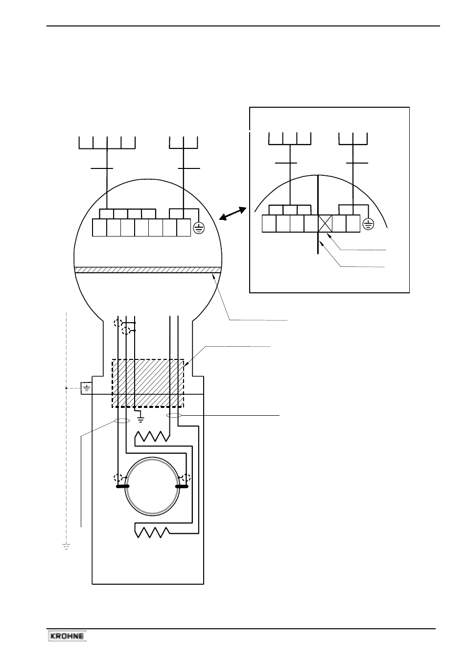
Connection diagram 1: Standard cables
Flow tube
Hazardous locations
of Zone 1 and 2
E
IFS x000…-EEx
Primary Head
Intrinsically safe electrode circuits
Increased safe field coil circuit
Coil
B1 B
⊥ B2 I+ I L N
BINARY CURRENT
MAINS
OUTPUTS OUTPUT SUPPLY
TERMINAL
COMPARTMENT
Standard "EEx e" (Optional "EEx d")
ELECTRONICS COMPARTMENT (always "EEx d")
electrode circuits
field coil circuits
IFC 090-EEx
Signal Converter
PE
FE
SIGNAL IN-/OUTPUTS
L
N PE 100-230 Vac
L L FE 24
Vac/dc
E
Q
UI
P
O
T
E
NT
IA
L BONDI
NG
CO
NDU
CT
O
R
≥
4
m
m
2
(
O
P
T
IO
N
A
L)
Flameproof (EEx d) cable
feed-through
Field coil wires
B
A
E
Coil
E
lec
tr
ode c
abl
es
IFC 090i-EEx
Signal Converter
x x x x
1L 0L
PE
FE
INTRINSICALLY
SAFE
SIGNAL IN-/OUTPUTS
L
N PE 100-230 Vac
(i.e.
MODIS)
L L FE 24
Vac/dc
Separation plate
Unused terminal
OPTION: MODIS
Flameproof (EEx d)
terminal feed-through
B
A